 |
amxuuw00004616
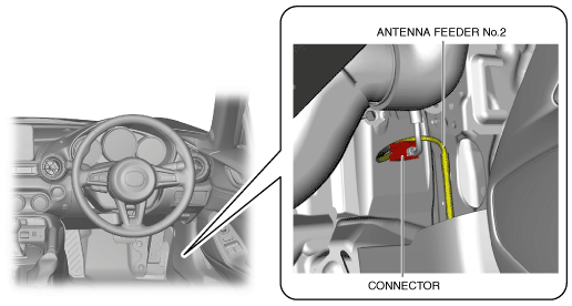
ANTENNA FEEDER NO.2 INSPECTION
id092000812500
Without Center Display
1. Disconnect the negative battery terminal. (See NEGATIVE BATTERY TERMINAL DISCONNECTION/CONNECTION.)
2. Disconnect the connector.
L.H.D.
amxuuw00004616
|
R.H.D.
amxzzw00003338
|
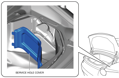
3. Remove the service hole cover on the trunk side trim (RH).
amxuuw00004617
|
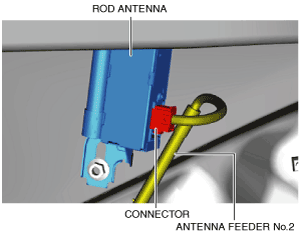
4. Disconnect the connector.
amxuuw00004618
|
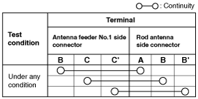
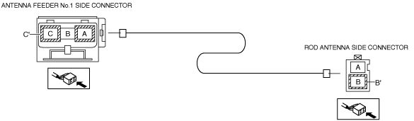
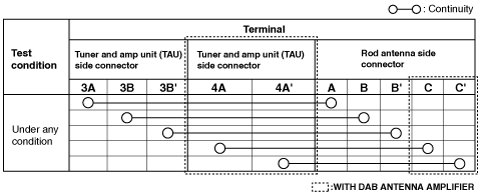
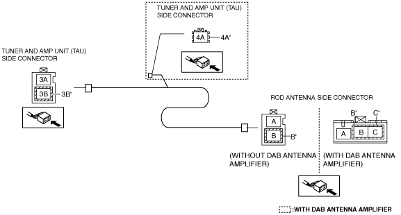
5. Verify that the continuity between antenna feeder No.2 terminals is as indicated in the table.
amxuuw00004619
|
amxuuw00004620
|
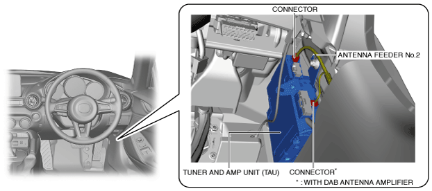
With Center Display
L.H.D.
1. Disconnect the negative battery terminal. (See NEGATIVE BATTERY TERMINAL DISCONNECTION/CONNECTION.)
2. Remove the following parts:
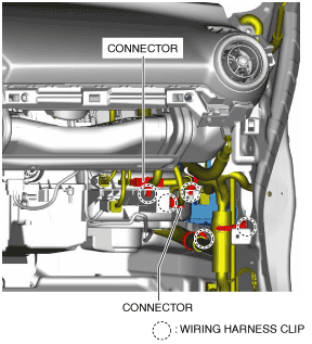
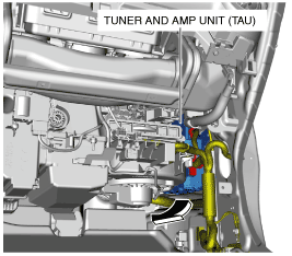
3. Disconnect the connectors.
amxuuw00002894
|
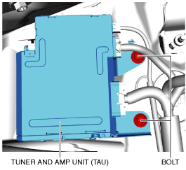
4. Pull out the wiring harness clips.
5. Remove the bolts.
amxuuw00004621
|
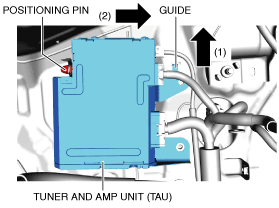
6. Move the tuner and amp unit (TAU) in the direction of arrow (1) shown in the figure and detach the guide from the body.
amxuuw00004622
|
7. Move the tuner and amp unit (TAU) in the direction of arrow (2) shown in the figure and detach the positioning pin from the body.
8. Pull out the tuner and amp unit (TAU) to the position where the connector can be pulled out in the direction of the arrow.
amxuuw00004623
|
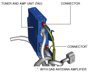
9. Disconnect the connectors.
amxzzw00003339
|
10. Remove the service hole cover on the trunk side trim (RH).
amxuuw00004617
|
11. Disconnect the connector.
amxuuw00004618
|
12. Verify that the continuity between antenna feeder No.2 terminals is as indicated in the table.
amxzzw00003340
|
amxzzw00003341
|
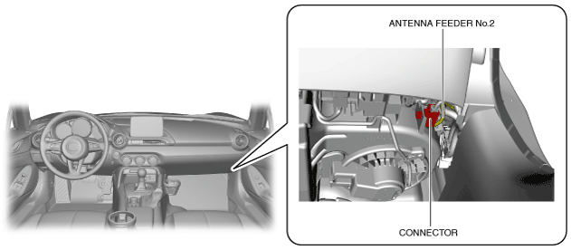
R.H.D.
1. Disconnect the negative battery terminal. (See NEGATIVE BATTERY TERMINAL DISCONNECTION/CONNECTION.)
2. Disconnect the connectors.
amxzzw00003342
|
3. Remove the service hole cover on the trunk side trim (RH).
amxuuw00004617
|
4. Disconnect the connector.
amxuuw00004618
|
5. Verify that the continuity between antenna feeder No.2 terminals is as indicated in the table.
amxzzw00003340
|
amxzzw00003341
|