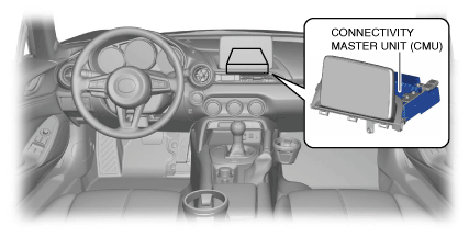
CONNECTIVITY MASTER UNIT [WITH CENTER DISPLAY]


id0920zz113400


Purpose, Function

•  The connectivity master unit (CMU) controls the entire system such as communication between mobile devices and Bluetooth®, and the sending/receiving of video/audio signals from units related to the entertainment system.

Bluetooth® communication function

•  The CMU uses the integrated Bluetooth® driver and antenna to perform communication between Bluetooth®-enabled devices and Bluetooth®.
•  To perform Bluetooth® communication, pairing of a Bluetooth®-enabled device with the CMU is required to specify the device. For the pairing method, refer to the [Bluetooth® PAIRING PROCEDURE] in the workshop manual.

Specification

Item

Content

Compatible profiles
A2DP 1.0/1.2 (Advanced audio distribution profile)
A2DP is a profile for transmitting high quality audio data by means of a Bluetooth® device and wireless transmission technology.
AVRCP 1.0/1.3/1.4 (Audio/video remote control profile)
AVRCP is a profile which provides a standard interface which controls television and audio devices. The function differs depending on the version.
Maximum number of programmable devices
7
Number of Bluetooth®-enabled devices which can be used simultaneously
2*1

*1  :A Hands-free call can be placed using another Bluetooth®-enabled device during audio playback using the other Bluetooth®-enabled device.
Note
•  The profile indicates the wireless communication standard. If the profile of the Bluetooth®-enabled device differs from the CMU, wireless transmission may not be possible. In addition, depending on the profile version, the corresponding functions differ.


Operation signal reception function

•  The CMU controls units related to the entertainment system based on the following operation signals which are sent in conjunction with the user operations from the operation signal output unit.

Operation signal output unit

Operation signal

Center display
LVDS signal (touch position operation signal)
Commander switch
Commander switch operation signal
Steering switch
Steering switch operation signal
Voice recognition microphone
Voice signal (voice command)


LVDS*2 signal conversion function

Note
•  Communication between the CMU and the center display is performed via the LVDS communication line.
•  The CMU converts signals sent from the following units to a LVDS signal and displays each type of information in the center display.

Output unit

Video signal/display request signal

Tuner and amp unit (TAU)
•  Radio broadcast logo, album art, song name
•  Traffic information such as location and length of traffic jams
CD player
•  Playback file information (artist/song name)
DVD/CD player
•  DVD information (video) during playback
Auxiliary jack/USB port/SD card slot hub
•  Information for file being played (artist/song name)
Devices such as Bluetooth®-enabled mobile phones and or mobile devices such as Smartphones/Bluetooth®-enabled devices
•  Telephone book, incoming call record
•  Radio broadcast logo, album art, song name
Rear mount camera
•  Image at rear of vehicle
CMU
•  Incoming call pop-up screen display
•  Fuel economy monitor screen
•  Warning guidance screen display
•  Navigation screen display
•  Temperature warning pop-up screen display

•  By converting the video signal to a LVDS signal, the CMU is able to display stable images in the center display virtually free from the effects of noise.
•  The LVDS communication pathway between the CMU and the center display corresponds to HDCP*3.
*2  :The LVDS displays the electrical properties of the signal using low-voltage differential signaling. LVDS is a digital, wired transmission technology for the short range which adopts a differential interface having the characteristics of low voltage and low power consumption.
*3  :HDCP (High-bandwidth Digital Content Protection system) is a copyright protection technology which prevents content from being copied fraudulently. The pathway in a display device such as a display, which sends/receives digital signals from a video playback device such as a computer, is encrypted.


Audio transmission signal function

•  The CMU sends the audio signal received from the following units to the TAU.
―  Auxiliary jack/USB port/SD card slot hub
―  Devices such as Bluetooth®-enabled mobile phones and or mobile devices such as Smartphones/Bluetooth®-enabled devices
•  The CMU receives audio signals from the voice recognition microphone and performs control according to the commands.


Fuel economy function

•  The CMU receives the fuel consumption amount and travel distance information signal from the instrument cluster and displays it in the center display as the fuel economy monitor. For details, refer to the fuel economy monitor of the [CENTER DISPLAY]. (See CENTER DISPLAY [WITH CENTER DISPLAY].)


Navigation function

•  The CMU performs map display and route guidance based on the position information received from the GPS antenna and the map information received from the auxiliary jack/USB port/SD card slot hub. For details, refer to the [ENTERTAINMENT SYSTEM] navigation function. (See ENTERTAINMENT SYSTEM [WITH CENTER DISPLAY].)


Automatic configuration function

•  When the ignition is switched ON (engine off or on) after the CMU is replaced, the CMU reads the vehicle specification information sent from the instrument cluster, and stores the vehicle specification information.


On-board diagnostic function

•  The CMU has an on-board diagnostic function to facilitate system diagnosis. DTCs are stored in the event of a malfunction occurring. For details, refer to the [ON-BOARD DIAGNOSTIC]. (See ON-BOARD DIAGNOSTIC [ENTERTAINMENT SYSTEM (WITH CENTER DISPLAY)].)


Diagnostic assist function

•  The CMU has a diagnostic assist function which can verify the following. For details, refer to the [ON-BOARD DIAGNOSTIC]. (See ON-BOARD DIAGNOSTIC [ENTERTAINMENT SYSTEM (WITH CENTER DISPLAY)].)
―  Connection status of related parts
―  Operation status of related parts
―  Related part specifications


Construction

•  The CMU is located centrally inside the dashboard.
•  The CMU has an integrated Bluetooth® driver and antenna.
amxzzn00000993

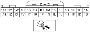
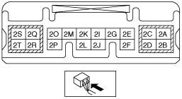
Input/output signal table

Terminal

Signal

1A
Rear mount camera power signal*5
1B
Rear mount camera signal ground*5
1C
Rear mount camera power supply*5
1D
Rear mount camera power supply ground*5
1E
1F
1G
1H
1I
1J
1K
iPod video signal*4
1L
iPod video signal ground*4
1M
Steering1 switch input
1N
Steering2 switch ground input
1O
Steering3 switch input
1P
Microphone connection detection
1Q
Microphone power supply
1R
Microphone power supply ground
1S
Microphone voice input (+)
1T
Microphone voice input (-)
1U
1V
1W
1X
1Y
CMU audio output LH (+)
1Z
CMU audio output LH (-)
1AA
CMU audio output RH (+)
1AB
CMU audio output RH (-)
2A
2B
2C
Ground
2D
Ground
2E
HS-CAN_H
2F
HS-CAN_L
2G
2I
Local HS-CAN_H
2J
Local HS-CAN_L
2K
LIN communication
2L
Ground
2M
2O
RS485 signal (+)
2P
RS485 signal (-)
2Q
ACC
2R
B+
2S
2T
3A
3B
LVDS (+)
3C
3D
LVDS (-)
4A
Ground
4B
USB data (+)
4C
USB power supply
4D
USB data (-)
5A
GPS
5A'
Ground

*4  :VIN serial No. 100001—
*5  :With parking assist system

Operation

•  For the CMU operation, refer to the [ENTERTAINMENT SYSTEM]. (See ENTERTAINMENT SYSTEM [WITH CENTER DISPLAY].)

Fail-safe

•  If the CMU receives an electrical signal (LVDS signal) of a temperature of approx. 82 °C {180 °F} or more from the center display, it performs the following controls:
―  Sends a temperature warning pop-up screen display request signal to the center display and displays the temperature warning pop-up screen on the LCD.
―  Temporarily lowers the brightness of the center display LCD. This is to protect the center display LCD and the circuit.