|
1
|
RECORD SNAPSHOT DATA AND DIAGNOSTIC MONITORING TEST RESULTS TO UTILIZE WITH REPEATABILITY VERIFICATION
-
Note
-
• Recording can be facilitated using the screen capture function of the PC.
• Record the snapshot data and DIAGNOSTIC MONITORING TEST RESULTS (fuel system related) on the repair order.
|
—
|
Go to the next step.
|
|
2
|
DETERMINE WHETHER MALFUNCTION IS PAST OR PRESENT
-
Note
-
• When clearing the DTC, the snap shot data is also cleared at the same time. Snap shot data is recorded if it is not recorded in Step 1.
• Using the M-MDS, clear the DTC from the EVP control unit.
• Switch the ignition ON (engine off).
• Using the M-MDS, perform the EVP control unit DTC inspection.
• Is the same DTC present?
|
Yes
|
Go to Step 7.
|
|
No
|
Go to the next step.
|
|
3
|
VERIFY DTC REPEATABILITY
• Switch the ignition ON (engine off).
• Access the following EVP control unit PIDs using the M-MDS:
-
― VP_MV
― VP_PV
• Access the simulation item VPS_FBK using the M-MDS.
• Verify PID VP_MV and VP_PV when the electric vacuum pump is operated by simulation item VPS_FBK.
• Are VP_MV and VP_PV PIDs within specification?
Specification:
-
VP_MV: Below 0.8 V (VPS_FBK On), 4.1—8.7 V (VPS_FBK Off)
VP_PV: 8.0—17.4 V (VPS_FBK On), 4.1—8.7 V (VPS_FBK Off)
|
Yes
|
Go to the next step.
|
|
No
|
Go to Step 7.
|
|
4
|
DRIVE VEHICLE THEN VERIFY DTC REPEATABILITY BASED ON SERVICE QUESTIONING RESULTS AND SNAP SHOT DATA
• Switch the ignition ON (engine off).
• Access the following EVP control unit PIDs using the M-MDS:
-
― VP_MV
― VP_PV
― VPS_FBK
• Drive the vehicle based on the service questions content and snap shot data driving conditions.
• Are VP_MV and VP_PV PIDs within specification, while the vehicle is driven?
Specification:
-
VP_MV: Below 0.8 V (VPS_FBK On), 4.1—8.7 V (VPS_FBK Off)
VP_PV: 8.0—17.4 V (VPS_FBK On), 4.1—8.7 V (VPS_FBK Off)
|
Yes
|
Go to the next step.
|
|
No
|
Go to Step 7.
|
|
5
|
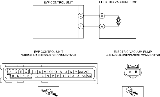
INSPECT ELECTRIC VACUUM PUMP CIRCUITS FOR SHORT TO EACH OTHER
• Switch the ignition OFF.
• Disconnect the negative battery cable.
• Disconnect the electric vacuum pump and EVP control unit connectors.
• Inspect for continuity between electric vacuum pump terminals A and B (wiring harness-side).
• Is there continuity?
|
Yes
|
Refer to the wiring diagram and verify whether or not there is a common connector in the followings:
• Electric vacuum pump terminal B—EVP control unit terminal C
• Electric vacuum pump terminal A—EVP control unit terminal E
If there is a common connector:
• Determine the malfunctioning part by inspecting the common connector and the terminal for corrosion, damage, or pin disconnection, and the common wiring harness for a short to each other.
• Repair or replace the malfunctioning part.
If there is no common connector:
• Repair or replace the wiring harness which has a short to each other.
Go to the next step.
|
|
No
|
Go to the next step.
|
|
6
|
VERIFY DTC REPEATABILITY AND DETERMINE IF MALFUNCTION CAUSE IS EVP CONTROL UNIT
• Connect the electric vacuum vacuum pump and EVP control unit connectors.
• Connect the negative battery cable.
• Using the M-MDS, clear the DTC from the EVP control unit.
• Switch the ignition ON (engine off).
• Using the M-MDS, perform the EVP control unit DTC inspection.
• Is the same DTC present?
|
Yes
|
Replace the EVP control unit, then go to Step 11.
|
|
No
|
DTC troubleshooting completed.
Explain to the customer that there are no malfunctions with the vehicle based on the contents of the servicing.
|
|
7
|
INSPECT ELECTRIC VACUUM PUMP CONNECTOR CONDITION
• Switch the ignition OFF.
• Disconnect the negative battery cable.
• Disconnect the electric vacuum pump connector.
• Inspect for poor connection (such as damaged/pulled-out pins, corrosion).
• Is the connector normal?
|
Yes
|
Go to the next step.
|
|
No
|
Repair or replace the connector and/or terminals, then go to Step 10.
|
|
8
|
INSPECT EVP CONTROL UNIT CONNECTOR CONDITION
• Disconnect the EVP control unit connector.
• Inspect for poor connection (such as damaged/pulled-out pins, corrosion).
• Is the connector normal?
|
Yes
|
Go to the next step.
|
|
No
|
Repair or replace the connector and/or terminals, then go to Step 10.
|
|
9
|
INSPECT ELECTRIC VACUUM PUMP CIRCUITS FOR SHORT TO EACH OTHER
• Verify that the electric vacuum pump and EVP control unit connectors are disconnected.
• Inspect for continuity between electric vacuum pump terminals A and B (wiring harness-side)
• Is there continuity?
|
Yes
|
Refer to the wiring diagram and verify whether or not there is a common connector in the followings:
• Electric vacuum pump terminal B—EVP control unit terminal C
• Electric vacuum pump terminal A—EVP control unit terminal E
If there is a common connector:
• Determine the malfunctioning part by inspecting the common connector and the terminal for corrosion, damage, or pin disconnection, and the common wiring harness for a short to each other.
• Repair or replace the malfunctioning part.
If there is no common connector:
• Repair or replace the wiring harness which has a short to each other.
Go to the next step.
|
|
No
|
Replace the electric vacuum pump, then go to the next step.
|
|
10
|
VERIFY DTC TROUBLESHOOTING COMPLETED
• Using the M-MDS, clear the DTC from the EVP control unit.
• Using the M-MDS, perform the EVP control unit DTC inspection.
• Is the same DTC present?
|
Yes
|
Repeat the inspection from Step1.
If the malfunction recurs, replace the EVP control unit, then go to the next step.
|
|
No
|
Go to the next step.
|
|
11
|
VERIFY NO DTC IS PRESENT
• Are any DTCs present?
|
Yes
|
Go to the applicable DTC inspection.
|
|
No
|
DTC troubleshooting completed.
|