 |
amxzzw00004067
PARKING BRAKE LEVER REMOVAL/INSTALLATION
id041200801600
1. Disconnect the negative battery cable. (See NEGATIVE BATTERY CABLE DISCONNECTION/CONNECTION.)
2. Remove the following parts:
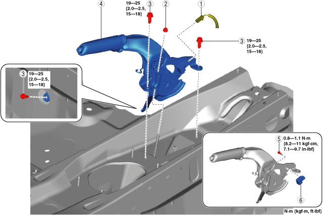
3. Remove in the order indicated in the table.
4. Install in the reverse order of removal.
5. After installation, inspect the parking brake lever stroke. (See PARKING BRAKE LEVER INSPECTION.)
amxzzw00004067
|
|
1
|
Parking brake switch connector
|
|
2
|
Adjusting nut
|
|
3
|
Bolt
(See Bolt Installation Note.)
|
|
4
|
Parking brake lever
|
|
5
|
Bolt
|
|
6
|
Parking brake switch
|
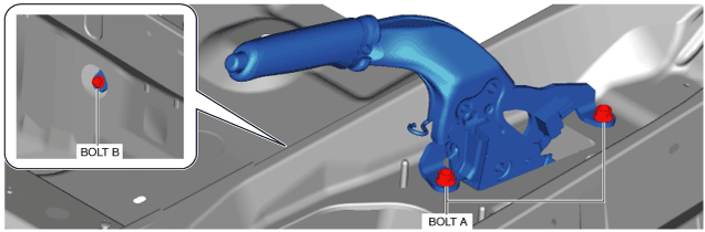
Bolt Installation Note
1. Tighten the bolt A to the specified torque.
amxuuw00005115
|
2. Tighten the bolt B to the specified torque.