|
amxuuw00005669
TCM INSPECTION [SJ6A-EL]
id051311250700
1. Measure the terminal voltage of the TCM using a tester.
amxuuw00005669
|
Terminal Voltage Table (Reference)
|
Terminal |
Connected to |
Test Condition |
Specification |
Inspection item(s) |
|---|---|---|---|---|
|
1A
|
Turbine sensor
|
• Inspect using the wave profile.
|
• Inspect the turbine sensor
• Inspect the related wiring harness
|
|
|
1B
|
Turbine sensor
|
Ignition switch ON
|
Approx. 2.5 V
|
• Inspect the turbine sensor
• Inspect the related wiring harness
|
|
1C
|
VSS
|
Ignition switch ON
|
Approx. 2.5 V
|
• Inspect the VSS
• Inspect the related wiring harness
|
|
1D
|
VSS
|
• Inspect using the wave profile.
|
• Inspect the VSS
• Inspect the related wiring harness
|
|
|
1E
|
Sensor shield
|
Under any condition
|
Below 1.0 V
|
• Inspect the related wiring harness
|
|
1F
|
—
|
—
|
—
|
—
|
|
1G
|
—
|
—
|
—
|
—
|
|
1H
|
Sensor shield
|
Under any condition
|
Below 1.0 V
|
• Inspect the related wiring harness
|
|
1I
|
—
|
—
|
—
|
—
|
|
1J
|
—
|
—
|
—
|
—
|
|
1K
|
TR switch
|
P position
|
B+
|
• Inspect the TR switch
• Inspect the related wiring harness
|
|
R position
|
B+
|
|||
|
N position
|
B+
|
|||
|
D position
|
Below 1.0 V
|
|||
|
M position
|
Below 1.0 V
|
|||
|
1L
|
—
|
—
|
—
|
—
|
|
1M
|
TR switch
|
P position
|
B+
|
• Inspect the TR switch
• Inspect the related wiring harness
|
|
R position
|
Below 1.0 V
|
|||
|
N position
|
B+
|
|||
|
D position
|
B+
|
|||
|
M position
|
B+
|
|||
|
1N
|
TR switch
|
P position
|
B+
|
• Inspect the TR switch
• Inspect the related wiring harness
|
|
R position
|
B+
|
|||
|
N position
|
Below 1.0 V
|
|||
|
D position
|
B+
|
|||
|
M position
|
B+
|
|||
|
1O
|
TR switch
|
P position
|
Below 1.0 V
|
• Inspect the TR switch
• Inspect the related wiring harness
|
|
R position
|
B+
|
|||
|
N position
|
B+
|
|||
|
D position
|
B+
|
|||
|
M position
|
B+
|
|||
|
1P
|
—
|
—
|
—
|
—
|
|
1Q
|
TFT check connector
|
Under any condition
|
B+
|
• Inspect the related wiring harness
|
|
1R
|
IG1 relay
|
Ignition switch OFF
|
Below 1.0 V
|
• Inspect the IG1 relay
(See RELAY INSPECTION)
• Inspect the related wiring harness
|
|
Ignition switch ON
|
B+
|
|||
|
1S
|
—
|
—
|
—
|
—
|
|
1T
|
—
|
—
|
—
|
—
|
|
1U
|
—
|
—
|
—
|
—
|
|
1V
|
—
|
—
|
—
|
—
|
|
1W
|
—
|
—
|
—
|
—
|
|
1X
|
—
|
—
|
—
|
—
|
|
1Y
|
Electric AT oil pump driver relay (With i-stop)
|
Idle
|
Below 1.0 V
|
• Inspect the electric AT oil pump driver relay
(See RELAY INSPECTION)
• Inspect the related wiring harness
|
|
During i-stop operation
|
B+
|
|||
|
1Z
|
Electric AT oil pump driver control unit (With i-stop)
|
• Inspect using the wave profile.
|
• Inspect the electric AT oil pump driver control unit
• Inspect the related wiring harness
|
|
|
1AA
|
—
|
—
|
—
|
—
|
|
1AB
|
—
|
—
|
—
|
—
|
|
1AC
|
—
|
—
|
—
|
—
|
|
1AD
|
—
|
—
|
—
|
—
|
|
1AE
|
CAN related module
|
Because this terminal is for communication, determination using terminal voltage inspection is not possible. Perform the inspection using the DTC inspection.
|
||
|
1AF
|
Electric AT oil pump driver control unit (With i-stop)
|
• Inspect using the wave profile.
|
• Inspect the electric AT oil pump driver control unit
• Inspect the related wiring harness
|
|
|
1AG
|
—
|
—
|
—
|
—
|
|
1AH
|
—
|
—
|
—
|
—
|
|
1AI
|
CAN related module
|
Because this terminal is for communication, determination using terminal voltage inspection is not possible. Perform the inspection using the DTC inspection.
|
||
|
2A
|
—
|
—
|
—
|
—
|
|
2B
|
—
|
—
|
—
|
—
|
|
2C
|
CAN related module
|
Because this terminal is for communication, determination using terminal voltage inspection is not possible. Perform the inspection using the DTC inspection.
|
||
|
2D
|
TCC control solenoid
|
• Inspect using the wave profile.
|
• Inspect the TCC control solenoid
• Inspect the related wiring harness
|
|
|
2E
|
Line pressure control solenoid
|
Idle and selector lever is at P position or N position
|
Below 1.0 V
|
• Inspect the line pressure control solenoid
• Inspect the related wiring harness
|
|
2F
|
—
|
—
|
—
|
—
|
|
2G
|
CAN related module
|
Because this terminal is for communication, determination using terminal voltage inspection is not possible. Perform the inspection using the DTC inspection.
|
||
|
2H
|
—
|
—
|
—
|
—
|
|
2I
|
—
|
—
|
—
|
—
|
|
2J
|
TFT sensor
|
ATF temperature 20°C {68°F}
|
Approx. 3.0 V
|
• Inspect the TFT sensor
• Inspect the related wiring harness
|
|
ATF temperature 40°C {104°F}
|
Approx. 2.1 V
|
|||
|
ATF temperature 60°C {140°F}
|
Approx. 1.4 V
|
|||
|
2K
|
—
|
—
|
—
|
—
|
|
2L
|
Shift solenoid G
|
• Inspect using the wave profile.
|
• Inspect the shift solenoid G
• Inspect the related wiring harness
|
|
|
2M
|
TFT sensor
|
Under any condition
|
Below 1.0 V
|
• Inspect the TFT sensor
• Inspect the related wiring harness
|
|
2N
|
—
|
—
|
—
|
—
|
|
2O
|
Shift solenoid F
|
• Inspect using the wave profile.
|
• Inspect the shift solenoid F
• Inspect the related wiring harness
|
|
|
2P
|
GND
|
Under any condition
|
Below 1.0 V
|
• Inspect the related wiring harness
|
|
2Q
|
TCC control solenoid
|
• Inspect using the wave profile.
|
• Inspect the TCC control solenoid
• Inspect the related wiring harness
|
|
|
2R
|
Line pressure control solenoid
|
• Inspect using the wave profile.
|
• Inspect the line pressure control solenoid
• Inspect the related wiring harness
|
|
|
2S
|
Shift solenoid D
|
1GR
|
Below 1.0 V
|
• Inspect the shift solenoid D
• Inspect the related wiring harness
|
|
2GR
|
Below 1.0 V
|
|||
|
3GR
|
Below 1.0 V
|
|||
|
4GR
|
Below 1.0 V
|
|||
|
5GR
|
B+
|
|||
|
6GR
|
B+
|
|||
|
2T
|
—
|
—
|
—
|
—
|
|
2U
|
—
|
—
|
—
|
—
|
|
2V
|
Shift solenoid E
|
1GR
|
B+
|
• Inspect the shift solenoid E
• Inspect the related wiring harness
|
|
2GR
|
B+
|
|||
|
3GR
|
B+
|
|||
|
4GR
|
B+
|
|||
|
5GR
|
Below 1.0 V
|
|||
|
6GR
|
Below 1.0 V
|
|||
|
2W
|
—
|
—
|
—
|
—
|
|
2X
|
GND
|
Under any condition
|
Below 1.0 V
|
• Inspect the related wiring harness
|
|
2Y
|
Shift solenoid G
|
• Inspect using the wave profile.
|
• Inspect the shift solenoid G
• Inspect the related wiring harness
|
|
|
2Z
|
Shift solenoid F
|
• Inspect using the wave profile.
|
• Inspect the shift solenoid F
• Inspect the related wiring harness
|
|
|
2AA
|
Shift solenoid C
|
1GR
|
B+
|
• Inspect the shift solenoid C
• Inspect the related wiring harness
|
|
2GR
|
B+
|
|||
|
3GR
|
B+
|
|||
|
4GR
|
Below 1.0 V
|
|||
|
5GR
|
Below 1.0 V
|
|||
|
6GR
|
Below 1.0 V
|
|||
|
2AB
|
Shift solenoid B
|
1GR
|
B+
|
• Inspect the shift solenoid B
• Inspect the related wiring harness
|
|
2GR
|
B+
|
|||
|
3GR
|
Below 1.0 V
|
|||
|
4GR
|
Below 1.0 V
|
|||
|
5GR
|
Below 1.0 V
|
|||
|
6GR
|
B+
|
|||
|
2AC
|
—
|
—
|
—
|
—
|
|
2AD
|
ACC relay
|
Ignition switch OFF
|
Below 1.0 V
|
• Inspect the ACC relay
(See RELAY INSPECTION)
• Inspect the related wiring harness
|
|
Ignition switch ACC
|
B+
|
|||
|
2AE
|
Battery
|
Under any condition
|
B+
|
• Inspect the Battery
(See BATTERY INSPECTION)
• Inspect the related wiring harness
|
|
2AF
|
Shift solenoid A
|
1GR
|
Below 1.0 V
|
• Inspect the shift solenoid A
• Inspect the related wiring harness
|
|
2GR
|
B+
|
|||
|
3GR
|
B+
|
|||
|
4GR
|
B+
|
|||
|
5GR
|
B+
|
|||
|
6GR
|
B+
|
|||
|
2AG
|
—
|
—
|
—
|
—
|
|
2AH
|
—
|
—
|
—
|
—
|
|
2AI
|
Battery
|
Under any condition
|
B+
|
• Inspect the Battery
(See BATTERY INSPECTION)
• Inspect the related wiring harness
|
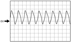
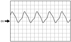
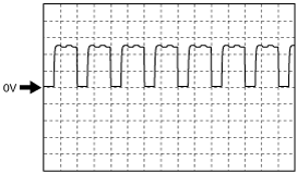
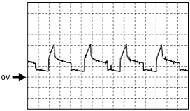
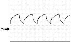
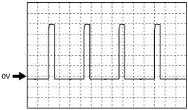
Inspection Using An Oscilloscope (Reference)
Turbine sensor (+)
amxuuw00000400
|
Vehicle speed (+)
amxuuw00000401
|
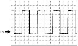
Electric AT oil pump driver control unit
amxzzw00003805
|
Electric AT oil pump driver control unit
amxzzw00003806
|
TCC control solenoid control (-)
ar8uuw00003100
|
Shift solenoid G control (-)
amxuuw00000405
|
Shift solenoid F control (-)
amxuuw00000403
|
TCC control solenoid control (+)
ar8jjw00000566
|
Line pressure control solenoid control (+)
ar8uuw00003099
|
Shift solenoid G control (+)
amxuuw00000404
|
Shift solenoid F control (+)
ar8uuw00003099
|