 |
amxuuw00002845
TURBINE SENSOR INSPECTION [SJ6A-EL]
id051311251900
1. Disconnect the negative battery cable. (See NEGATIVE BATTERY CABLE DISCONNECTION/CONNECTION.)
2. Remove the selector lever knob. (See AUTOMATIC TRANSMISSION SHIFT MECHANISM REMOVAL/INSTALLATION.)
3. Remove the shift panel component. (See SHIFT PANEL REMOVAL/INSTALLATION.)
4. Remove the upper panel. (See UPPER PANEL REMOVAL/INSTALLATION.)
5. Remove the parking brake lever boot panel. (See PARKING BRAKE LEVER BOOT PANEL REMOVAL/INSTALLATION.)
6. Remove the rear console. (See REAR CONSOLE REMOVAL/INSTALLATION.)
7. Remove the front console panel. (See FRONT CONSOLE PANEL REMOVAL/INSTALLATION.)
8. Remove the front console component. (See FRONT CONSOLE REMOVAL/INSTALLATION.)
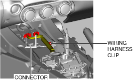
9. Disconnect the connector and wiring harness clip.
amxuuw00002845
|
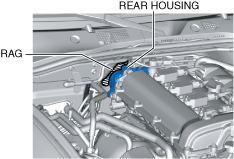
10. Place a clean rag behind the engine so that the engine does not contact the rear housing when it is tilted.
amxuuw00004812
|
11. Remove the front crossmember under cover. (See FRONT CROSSMEMBER UNDER COVER REMOVAL/INSTALLATION.)
12. Disconnect the control rod from the selector lever component. (See AUTOMATIC TRANSMISSION SHIFT MECHANISM REMOVAL/INSTALLATION.)
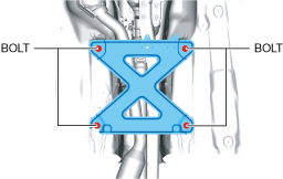
13. Remove the tunnel member.
amxuuw00003817
|
14. Disconnect the HO2S connector. (See HEATED OXYGEN SENSOR (HO2S) REMOVAL/INSTALLATION [SKYACTIV-G 1.5, SKYACTIV-G 2.0].)
15. Disconnect the TWC from the exhaust manifold (WU-TWC). (See EXHAUST SYSTEM REMOVAL/INSTALLATION [SKYACTIV-G 1.5, SKYACTIV-G 2.0].)
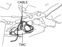
16. Suspend the TWC using a cable as shown in the figure.
amxuuw00002847
|
17. Remove the power plant frame. (See POWER PLANT FRAME REMOVAL [M66M-D].)(See POWER PLANT FRAME INSTALLATION [M66M-D].)
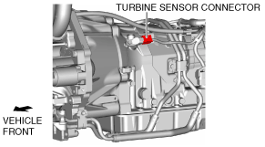
18. Tilt the transmission while being careful not to allow parts on the back of the engine to contact the vehicle body.
19. Disconnect the turbine sensor connector.
amxuuw00003526
|
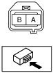
20. Measure the resistance between the turbine sensor terminals A and B.
ardjjw00004974
|