 |
amxuuw00004657
INDICATOR UNIT INSPECTION
id092200037600
Terminal Voltage Inspection
1. Disconnect the negative battery cable. (See NEGATIVE BATTERY CABLE DISCONNECTION/CONNECTION.)
2. Remove the following parts:
3. Remove the indicator unit with the connector still connected. (See INDICATOR UNIT REMOVAL/INSTALLATION.)
4. Connect the negative battery cable. (See NEGATIVE BATTERY CABLE DISCONNECTION/CONNECTION.)
5. Verify that the voltages of each of the terminals are as indicated in the terminal voltage table (reference).
Terminal Voltage Table (Reference)
amxuuw00004657
|
|
Terminal |
Signal name |
Connected to |
Measurement conditions |
Voltage (V) |
Inspection item(s) |
|
|---|---|---|---|---|---|---|
|
A
|
Power supply (IG1)
|
IG1 relay
|
Ignition switch ON (engine off or on)
|
B+
|
• METER1 10 A fuse
• IG1 relay
• Related wiring harness
|
|
|
Ignition switch off or ACC
|
1.0 or less
|
|||||
|
B
|
Power supply
|
• INTERIOR 15 A fuse
• ROOM 25 A fuse
|
Under any condition
|
B+
|
• INTERIOR 15 A fuse
• ROOM 25 A fuse
• Battery
• Related wiring harness
|
|
|
C
|
—
|
—
|
—
|
—
|
—
|
|
|
D*1
|
Seat warmer switch signal
|
Seat warmer control unit
|
Because this terminal is for communication, determination using terminal voltage inspection is not possible.
|
|||
|
E*2
|
Passenger air bag deactivation (PAD) ON indicator
|
Instrument cluster
|
Ignition switched ON (engine off)
|
Passenger's seat is unoccupied (PAD ON indicator light turns off) and light switch at OFF position
|
1.0 or less
|
• Instrument cluster
• Related wiring harness
|
|
Passenger's seat is unoccupied (PAD ON indicator light turns off) and light switch at TNS (Parking Lights) position
|
Approx. 11
|
|||||
|
Adult is seated in passenger’s seat (PAD ON indicator light turns on)
|
Approx. 4
|
|||||
|
F
|
Ground
|
Body ground
|
Under any condition
|
1.0 or less
|
• Body ground
• Related wiring harness
|
|
|
G
|
Instrument cluster signal
|
Instrument cluster
|
Because this terminal is for communication, determination using terminal voltage inspection is not possible.
|
|||
|
H*2
|
Retractable hardtop indicator
|
Retractable hardtop control module
|
Ignition switch ON (engine off or on)
|
Retractable hardtop open or close operation
|
approx. 10
|
• Retractable hardtop control module
• Related wiring harness
|
|
Other
|
1.0 or less
|
|||||
|
I*2
|
Retractable hardtop switch
|
Retractable hardtop control module
|
Ignition switch ON (engine off or on)
|
Keep retractable hardtop switch push
|
1.0 or less
|
• Retractable hardtop control module
• Related wiring harness
|
|
Release retractable hardtop switch
|
approx. 10
|
|||||
|
J*3
|
Passenger air bag deactivation (PAD) OFF indicator
|
Instrument cluster
|
Ignition switched ON (engine off)
|
Passenger's seat is unoccupied, approx. 60 s (during PAD OFF indicator illumination)
|
Approx. 11
|
• Instrument cluster
• Related wiring harness
|
|
Adult is seated in passenger’s seat (PAD OFF indicator light turns off) and light switch at OFF position
|
Approx. 4
|
|||||
|
Adult is seated in passenger’s seat (PAD OFF indicator light turns off) and light switch at TNS (Parking Lights) position
|
1.0 or less
|
|||||
LED Illumination Inspection
When using M-MDS
1. Connect the M-MDS to the DLC-2.
2. After the vehicle is identified, select the following items from the initialization screen of the M-MDS.
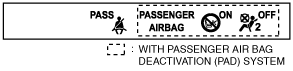
3. Using the simulation function item LCD_SEG, verify that the warning/indicator lights are displayed as shown in the following figure.
amxzzw00003291
|
When not using M-MDS
1. Disconnect the negative battery cable. (See NEGATIVE BATTERY CABLE DISCONNECTION/CONNECTION.)
2. Remove the following parts:
3. Remove the indicator unit with the connector still connected. (See INDICATOR UNIT REMOVAL/INSTALLATION.)
4. Connect the negative battery cable. (See NEGATIVE BATTERY CABLE DISCONNECTION/CONNECTION.)
5. Switch the ignition ON (engine off or on).
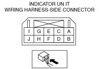
6. Using a jumper wire, connect indicator unit terminal G and body ground for 5 s or more.
amxuuw00004659
|
7. Verify that the warning/indicator lights are displayed as shown in the figure.
amxzzw00003291
|