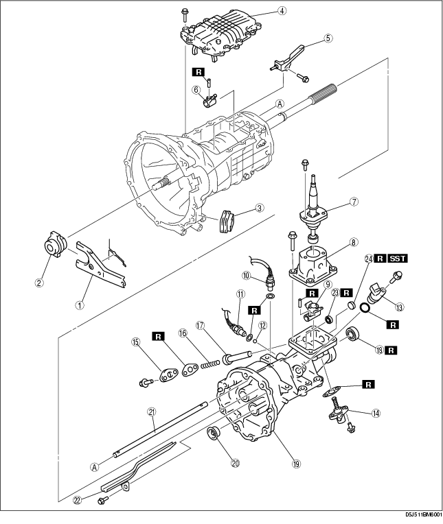
1. Disassemble in the order indicated in the table.
|
1
|
Release fork
|
|
2
|
Release collar
|
|
3
|
Dust boot
|
|
4
|
Top cover, shift component
(See Top Cover Disassembly Note.)
|
|
5
|
Oil passage
|
|
6
|
Control lever
|
|
7
|
Change lever component
|
|
8
|
Control case
|
|
9
|
Control rod end
|
|
10
|
Back-up light switch
|
|
11
|
Neutral switch
|
|
12
|
Steel ball
|
|
13
|
Vehicle speed sensor, hole cover
|
|
14
|
Select spindle component
|
|
15
|
Spring cap
|
|
16
|
Select lock spindle spring
|
|
17
|
Select lock spindle
|
|
18
|
Oil seal (extension housing)
|
|
19
|
Extension housing
|
|
20
|
Funnel
|
|
21
|
Control rod
|
|
22
|
Oil passage
|
|
23
|
Oil seal (control rod)
|
|
24
|
Sealing cap
(See Sealing Cap Disassembly Note.)
|
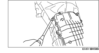
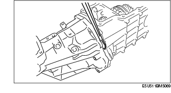
1. Pry the seal open at the projection on the case using a flathead screwdriver or similar tool as shown in the figure, and then remove the control case.
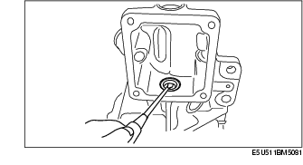
1. Remove the oil seal using a flathead screwdriver as shown in the figure.
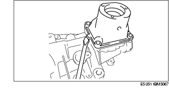
1. Pry the seal open at the projection on the case using a flathead screwdriver or similar tool as shown in the figure, and then remove the top cover.
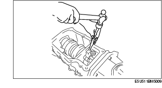
1. Remove the spring pin of the control lever using a pin punch in the figure.
2. Remove the spring pin of the control rod end using a pin punch in the figure.
3. Remove the extension housing component.
1. Using a flathead screwdriver, remove the oil seal as shown in the figure.
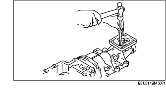
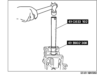
1. Remove the sealing cap using the SST.