1. Assemble in the order indicated in the table.
|
1
|
Oil seal (control rod)
|
|
2
|
Sealing cap
(See Sealing Cap Assembly Note.)
|
|
3
|
Control rod
|
|
4
|
Oil passage
|
|
5
|
Funnel
|
|
6
|
Extension housing
|
|
7
|
Control rod end
|
|
8
|
Select spindle component
|
|
9
|
Select lock spindle
|
|
10
|
Select lock spindle spring
|
|
11
|
Spring cap
|
|
12
|
Vehicle speed sensor, hole cover
|
|
13
|
Oil seal (extension housing)
|
|
14
|
Control lever
|
|
15
|
Oil passage
|
|
16
|
Top cover, shift component
(See Top Cover Assembly Note.)
|
|
17
|
Control case
(See Control Case Assembly Note.)
|
|
18
|
Change lever component
|
|
19
|
Steel ball
|
|
20
|
Neutral switch
|
|
21
|
Back-up light switch
|
|
22
|
Dust boot
|
|
23
|
Release collar
|
|
24
|
Release fork
|
1. Measure the depth A of the oil seal installation hole as shown in the figure.
2. Calculate the oil seal installation depth B.
3. Install the oil seal using the SST through the sealing cap hole as shown in the figure.

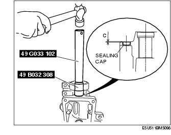
1. Install the sealing cap using the SST.
1. Apply specified oil to the lip of a new oil seal.
2. Install the oil seal evenly and gradually using the SST and a hammer.
1. Apply sealant to the contact surfaces of the extension housing and transmission case as shown in the figure.
2. Install the extension housing to the transmission case.
Tightening torque:1. Apply sealant to the contact surfaces of the transmission case and top cover as shown in the figure.
2. Install the top cover component to the transmission case.
Tightening torque:1. Apply sealant to the contact surfaces of the control case and extension housing as shown in the figure.
2. Install the control case to the extension housing.
Tightening torque:1. Apply specified grease to the areas shown in the figure.
2. Install the release collar and release fork.