 |
e5u513zw5005
VEHICLE SPEED SENSOR (VSS) REMOVAL/INSTALLATION [SJ6A-EL]
id051311252700
1. Remove the battery cover.
2. Disconnect the negative battery cable. (See BATTERY REMOVAL/INSTALLATION [L8, LF].)
3. Remove the tunnel member component.
4. Remove the middle pipe. (See EXHAUST SYSTEM REMOVAL/INSTALLATION [L8, LF].)
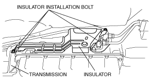
5. Remove the insulator.
e5u513zw5005
|
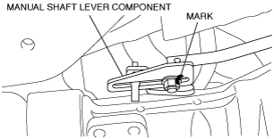
6. Mark the manual shaft lever component as shown in the figure.
e5u513zw5007
|
7. Separate the manual shaft lever component from the selector lever.
8. Disconnect the VSS connector.
9. Remove the VSS.
e5u513zw5033
|
10. Install the VSS.
11. Connect the VSS connector.
12. Align the mark of the manual shaft lever component as shown in the figure.
e5u513zw5007
|
13. Install the manual shaft lever component installation nut.
14. Install the insulator.
15. Install the middle pipe. (See EXHAUST SYSTEM REMOVAL/INSTALLATION [L8, LF].)
16. Install the tunnel member component.
17. Connect the negative battery cable. (See BATTERY REMOVAL/INSTALLATION [L8, LF].)
18. Install the battery cover.