 |
amxzzw00001339
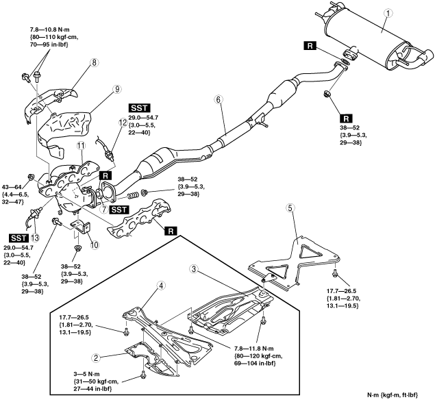
EXHAUST SYSTEM REMOVAL/INSTALLATION [L8, LF]
id0115a4800200
1. Remove the battery cover. (See BATTERY REMOVAL/INSTALLATION [L8, LF].)
2. Disconnect the negative battery cable. (See BATTERY REMOVAL/INSTALLATION [L8, LF].)
3. Remove in the order indicated in the table.
4. Remove the exhaust system insulator. (See Exhaust System Insulator Removal/installation Note.)
5. Install in the reverse order of removal.
amxzzw00001339
|
|
1
|
Main silencer
|
|
2
|
Under guard (LF MT)
|
|
3
|
Insulator (LF MT)
|
|
4
|
Member bracket (MT)
|
|
5
|
Tunnel member
|
|
6
|
Middle pipe
|
|
7
|
Seal ring
(See Seal Ring Removal Note.)
(See Seal Ring Installation Note.)
|
|
8
|
Exhaust manifold insulator (upper)
|
|
9
|
Exhaust manifold insulator (lower)
|
|
10
|
Exhaust manifold bracket
|
|
11
|
Exhaust manifold
|
|
12
|
HO2S
|
|
13
|
A/F sensor
|
Exhaust System Insulator Removal/installation Note
1. Remove the exhaust system insulator in the order shown in the figure.
2. Install in the reverse order of removal.
amxzzw00001340
|
|
1
|
Insulator (rear)
|
|
2
|
Insulator (middle)
|
|
3
|
Insulator (front)
|
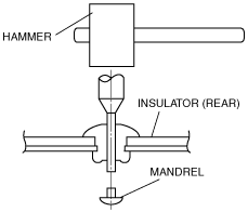
Insulator (Rear) Removal Note
1. Push out the mandrel using a hammer and punch (2—2.8 mm {0.08—0.11 in} diameter).
amxzzw00001341
|
2. Remove the flange using a drill (5 mm {0.20 in} drill bit).
ar8uuw00001479
|
Seal Ring Removal Note
1. Remove the seal ring using a flathead screwdriver being careful not to damage the pipe.
amxzzw00001342
|
Exhaust Manifold Insulator (Upper) Removal Note
1. Remove the battery and battery tray. (See BATTERY REMOVAL/INSTALLATION [L8, LF].)
2. Remove the drive belt. (See DRIVE BELT REPLACEMENT [L8, LF].)
3. Remove the under cover. (See TRANSVERSE MEMBER REMOVAL/INSTALLATION.)
4. Remove the suspension tower bar (joint) and (right side). (See FRONT SUSPENSION TOWER BAR REMOVAL/INSTALLATION.)
5. Remove the generator. (See GENERATOR REMOVAL/INSTALLATION [L8, LF].)
6. Remove the insulator.
amxzzw00001343
|
Exhaust Manifold Removal Note
1. Disconnect the A/F sensor connector and HO2S connector.
2. Move the water pipe and heater hose slightly out of the way.
amxzzw00001344
|
3. Disconnect the ventilation hose from the cylinder head. (See QUICK RELEASE CONNECTOR (EMISSION SYSTEM) REMOVAL/INSTALLATION [L8, LF].)
Seal Ring Installation Note
1. Temporarily install the seal ring to the pipe so that the seal ring is even with the flange.
amxzzw00001345
|
2. Install the SST to the seal ring so that the SST is even with the flange.
amxzzw00001346
|
3. Press in the seal ring by tapping the SST using a plastic hammer until the seal ring contacts the flange.
amxzzw00001347
|
Middle pipe Installation Note
1. Spray carbon remover (TB6601 or equivalent) on the flared section of the middle pipe.
am6zzw00002918
|
2. Remove the carbon adhering to the flared section shown in the figure using a nylon brush or sandpaper (No. 400 or equivalent).