 |
amxzzw00000200
TRANSMISSION RANGE (TR) SWITCH REMOVAL/INSTALLATION [SJ6A-EL]
id051311710200
1. Remove the battery cover.
2. Disconnect the negative battery cable. (See BATTERY REMOVAL/INSTALLATION [L8, LF].)
3. Remove the tunnel member component.
4. Remove the middle pipe.(See EXHAUST SYSTEM REMOVAL/INSTALLATION [L8, LF].)
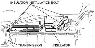
5. Remove the insulator.
amxzzw00000200
|
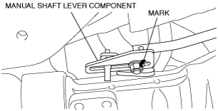
6. Mark the manual shaft lever component as shown in the figure.
e5u513zw5007
|
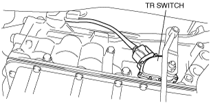
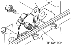
7. Separate the manual shaft lever component from selector lever.
8. Disconnect the TR switch connector.
e5u513zw5006
|
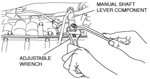
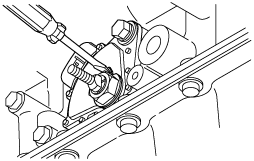
9. Rotate the manual shaft to the N position.
10. Set the adjustable wrench as shown in the figure to hold the manual shaft lever.
amxzzw00000201
|
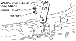
11. Remove the manual shaft nut.
12. Remove the washer and manual shaft lever component.
e5u513zw5009
|
13. Pry off the lock washer using a flathead screwdriver.
amxzzw00000202
|
14. Remove the nut and lock washer.
amxzzw00004265
|
15. Remove the TR switch.
amxzzw00000204
|
16. Rotate the manual shaft to the extension housing side fully and return two notches to set the N position.
amxzzw00000205
|
17. Install the TR switch and hand-tighten the new mounting bolts.
18. Verify the TR switch reference line and the notch of the manual shaft are aligned.
e5u513zw5081
|
19. Install the lock washer with the nut.
amxzzw00004265
|
20. Stake the lock washer using a flathead screwdriver.
amxzzw00000206
|
21. Tighten the TR switch mounting bolts.
22. Inspect for continuity between TR switch terminals E and H.
amxzzw00000207
|
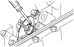
23. Install the manual shaft lever component and washer.
24. Set the adjustable wrench as shown in the figure to hold the manual shaft lever.
amxzzw00000208
|
25. Tighten the manual shaft nut using a torque wrench.
26. Shift the selector lever to the P position.
27. Turn the manual shaft lever to the P position.
28. Inspect TR switch continuity. (See TRANSMISSION RANGE (TR) SWITCH INSPECTION [SJ6A-EL].)
29. Connect the TR switch connector.
30. Align the mark of the manual shaft lever component as shown in the figure.
e5u513zw5007
|
31. Install the manual shaft lever component installation nut.
32. Install the insulator.
33. Install the middle pipe. (See EXHAUST SYSTEM REMOVAL/INSTALLATION [L8, LF].)
34. Install the tunnel member component.
35. Connect the negative battery cable. (See BATTERY REMOVAL/INSTALLATION [L8, LF].)
36. Install the battery cover.
37. Inspect TR switch operation. (See TRANSMISSION RANGE (TR) SWITCH INSPECTION [SJ6A-EL].)