 |
am2zzw00004337
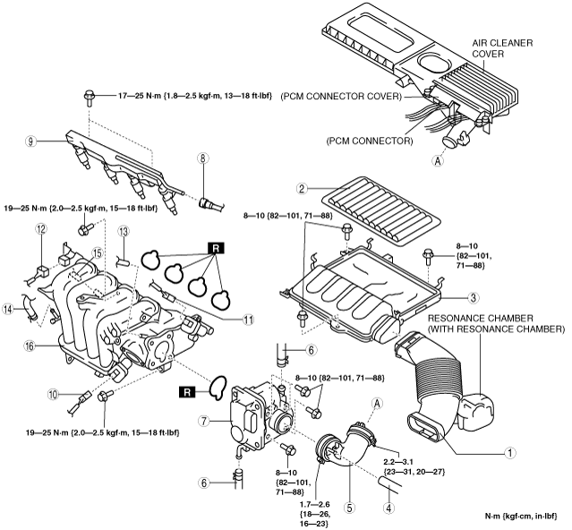
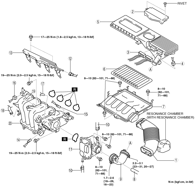
INTAKE-AIR SYSTEM REMOVAL/INSTALLATION [ZJ, ZY]
id0113a8801900
Without Set Bolt
1. Complete the “BEFORE SERVICE PRECAUTION”. (See BEFORE SERVICE PRECAUTION [ZJ, ZY].)
2. Disconnect the negative battery cable. (See BATTERY REMOVAL/INSTALLATION [ZJ, ZY].)
3. Remove in the order indicated in the table.
4. Install in the reverse order of removal.
5. Complete the “AFTER SERVICE PRECAUTION”. (See AFTER SERVICE PRECAUTION [ZJ, ZY].)
6. Add the engine coolant to the cooling system filler neck and the coolant reserve tank to replace that during servicing.
7. Inspect the engine coolant level. (See ENGINE COOLANT LEVEL INSPECTION [ZJ, ZY].)
8. Inspect for engine coolant leakage. (See ENGINE COOLANT LEAKAGE INSPECTION [ZJ, ZY].)
am2zzw00004337
|
|
1
|
Fresh-air duct
|
|
2
|
PCM connector cover
|
|
3
|
PCM connector
|
|
4
|
MAF/IAT sensor connector
|
|
5
|
Air cleaner cover
|
|
6
|
Air cleaner element
|
|
7
|
Air cleaner case
|
|
8
|
Ventilation hose (air hose side)
|
|
9
|
Air hose
(See Air Hose Removal Note.)
|
|
10
|
Engine coolant hose
|
|
11
|
Throttle body
|
|
12
|
Quick release connector
|
|
13
|
Fuel distributor component
|
|
14
|
Variable intake air shutter valve actuator connector (With variable intake air system)
|
|
15
|
Variable tumble shutter valve actuator connector
|
|
16
|
MAP sensor connector
|
|
17
|
Evaporative hose (to purge solenoid valve)
|
|
18
|
Vacuum hose (to master back)
|
|
19
|
PCV hose (intake manifold side)
|
|
20
|
Intake manifold
(See Intake Manifold Removal Note.)
|
With Set Bolt
1. Complete the “BEFORE SERVICE PRECAUTION”. (See BEFORE SERVICE PRECAUTION [ZJ, ZY].)
2. Disconnect the negative battery cable. (See BATTERY REMOVAL/INSTALLATION [ZJ, ZY].)
3. When removing the air cleaner cover, perform the following procedure and go to Step 6.
4. Set the air cleaner cover out of the way.
5. Remove in the order indicated in the table.
6. Install in the reverse order of removal.
7. Complete the “AFTER SERVICE PRECAUTION”. (See AFTER SERVICE PRECAUTION [ZJ, ZY].)
8. Add the engine coolant to the cooling system filler neck and the coolant reserve tank to replace that during servicing.
9. Inspect the engine coolant level. (See ENGINE COOLANT LEVEL INSPECTION [ZJ, ZY].)
10. Inspect for engine coolant leakage. (See ENGINE COOLANT LEAKAGE INSPECTION [ZJ, ZY].)
am2zzw00003649
|
|
1
|
Fresh-air duct
|
|
2
|
Air cleaner element
|
|
3
|
Air cleaner case
|
|
4
|
Ventilation hose (air hose side)
|
|
5
|
Air hose
(See Air Hose Removal Note.)
|
|
6
|
Engine coolant hose
|
|
7
|
Throttle body
|
|
8
|
Quick release connector
|
|
9
|
Fuel distributor component
|
|
10
|
Variable intake air shutter valve actuator connector (With variable intake air system)
|
|
11
|
Variable tumble shutter valve actuator connector
|
|
12
|
MAP sensor connector
|
|
13
|
Evaporative hose (to purge solenoid valve)
|
|
14
|
Vacuum hose (to master back)
|
|
15
|
PCV hose (intake manifold side)
|
|
16
|
Intake manifold
(See Intake Manifold Removal Note.)
|
Air Hose Removal Note
1. Move the purge solenoid valve slightly out of the way without removing the air hose.
Engine Coolant Hose Removal Note
1. Wrap a clean cloth around the cooling system cap and release the pressure by loosening the cap slowly.
2. Remove the engine coolant hose from the throttle body and plug the engine coolant hose quickly.
Intake Manifold Removal Note
1. Remove the EGR pipe (intake manifold side). (See EGR PIPE REMOVAL/INSTALLATION [ZJ, ZY].)
2. Remove all clips for securing wiring harnesses from the intake manifold.
3. Remove the intake manifold.
Engine Coolant Hose Installation Note
1. Remove the plug from the engine coolant hose and install the engine coolant hose to the throttle body quickly.
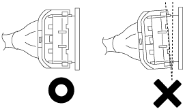
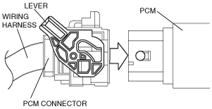
PCM Connector Connection Note
am2zzw00006958
|
1. Verify that the PCM connector lever is tilted towards the wiring harness side as shown in the figure.
am2zzw00006959
|
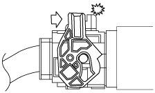
2. Insert the PCM connector straight until it contacts the PCM and verify that the lever reverts upward naturally.
3. Push the lever until a click is heard.
am2zzw00006960
|