 |
am2zzw00004838
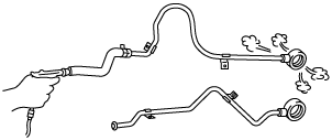
OIL COOLER REMOVAL/INSTALLATION [FN4A-EL]
id051701801600
1. Disconnect the negative battery cable.
2. Drain the engine coolant. (See ENGINE COOLANT REPLACEMENT [ZJ, ZY].)
3. Drain the ATF into a separate suitable container. (See AUTOMATIC TRANSAXLE FLUID (ATF) REPLACEMENT [FN4A-EL].)
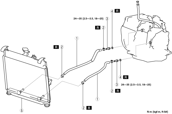
4. Remove in the order indicated in the table.
5. Install in the reverse order of removal.
6. Add the ATF. (See AUTOMATIC TRANSAXLE FLUID (ATF) REPLACEMENT [FN4A-EL].)
7. Connect the negative battery cable.
8. Perform the “Line Pressure Test“. (See MECHANICAL SYSTEM TEST [FN4A-EL].)
am2zzw00004838
|
|
1
|
Oil hose
|
|
2
|
Hose clamp
|
|
3
|
Connector bolt
|
|
4
|
Packing
|
|
5
|
Radiator (in tank oil cooler)
|
Radiator (In Tank Oil Cooler) Installation Note
1. The automatic transaxle oil cooler flushing must be performed whenever a transaxle is removed for service because the existing fluid may be contaminated, and to prevent contamination of new fluid.
2. Follow the instructions in the manufacturer’s publication for flushing operation.
Hose Clamp, Oil Hose Installation Note
1. Apply compressed air to the cooler-side opening, and blow any remaining grime and foreign material from the cooler pipes. Compressed air should be applied for no less than 1 min.
am2zzw00004842
|
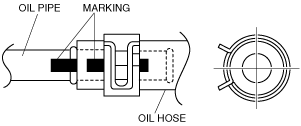
2. Align the marks, and slide the oil hose onto the oil pipe until it is fully seated as shown.
am2zzw00004839
|
am2zzw00004840
|
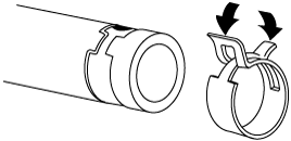
3. Install the new hose clamp onto the hose.
4. Verify that the hose clamp does not interfere with any other components.