CLUTCH COMPONENT DISASSEMBLY
id051700660700
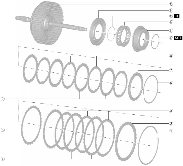
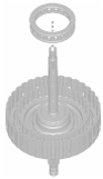
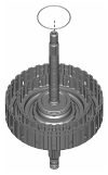
Structural view
|
1
|
Snap ring
|
|
2
|
Retaining plate
|
|
3
|
Drive plate
|
|
4
|
Driven plate
|
|
5
|
Wave spring
|
|
6
|
Snap ring
|
|
7
|
Retaining plate
|
|
8
|
Drive plate
|
|
9
|
Driven plate
|
|
10
|
Snap ring
|
|
11
|
Seal plate
|
|
12
|
Springs and retainer component
|
|
13
|
O-ring
|
|
14
|
High clutch piston
|
|
15
|
Drum and shaft component
|
Disassembly Procedure
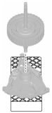
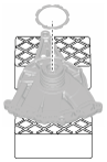
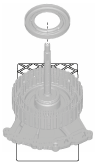
1. Perform a simple inspection of the low clutch and high clutch using the following procedure:
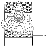
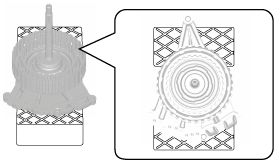
- (1) Set the oil pump on the workbench as shown in the figure.
-
-
Note
-
• Using the rubber plates, adjust the alignment surface of the oil pump with the transaxle case so that it is level.
A :Rubber plate
- (2) Assemble the thrust washer to the clutch component using the following procedure:
-
-
Note
-
• Thrust washer size: Inner diameter approx. 58.7 mm {2.31 in}
- 1) To prevent the thrust washer from dropping out, apply ATF (ATF FZ) to the thrust washer.
- 2) Assemble the thrust washer.
-
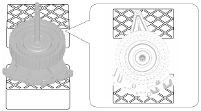
- (3) Assemble the parts assembled together in Step (2) to the oil pump.
-
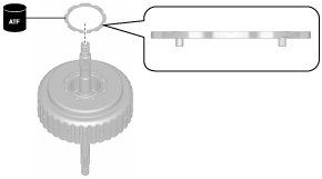
- (4) Blow compressed air into the oil passage shown in the figure and verify the operation condition of the low clutch.
-
-
Warning
-
• Always wear protective eye wear when using the air compressor. Otherwise, ATF or dirt particles blown off by the air compressor could get into the eyes.
-
Caution
-
• To prevent damage to parts, always use an air compressor which is adjusted to the indicated pressure.
-
Compressed air pressure
-
0.39—0.44 MPa {4.0—4.4 kgf/cm2, 57—63 psi}
-
• If there is a malfunction, verify the cause and repair the applicable part after disassembly.
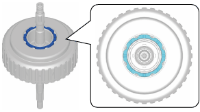
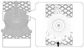
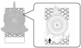
- (5) Blow compressed air into the oil passage shown in the figure and verify the operation condition of the high clutch.
-
-
Warning
-
• Always wear protective eye wear when using the air compressor. Otherwise, ATF or dirt particles blown off by the air compressor could get into the eyes.
-
Caution
-
• To prevent damage to parts, always use an air compressor which is adjusted to the indicated pressure.
-
Compressed air pressure
-
0.39—0.44 MPa {4.0—4.4 kgf/cm2, 57—63 psi}
-
• If there is a malfunction, verify the cause and repair the applicable part after disassembly.
- (6) Remove the clutch component.
-
- (7) Remove the thrust washer.
-
- (8) Take the oil pump off the rubber plates.
-
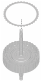
2. Remove the snap ring.
3. Remove the retaining plate.
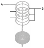
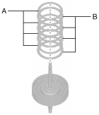
4. Remove the drive plates and driven plates.
A :Drive plate
B :Driven plate
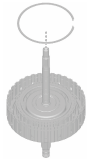
5. Remove the wave spring.
6. Remove the snap ring.
7. Remove the retaining plate.
8. Remove the drive plates and driven plates.
A :Drive plate
B :Driven plate
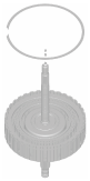
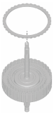
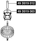
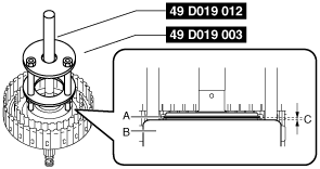
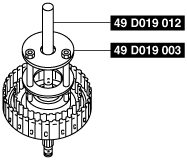
9. Remove the snap ring using the following procedure:
- (1) Install the SSTs.
-
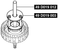
- (2) Set the SSTs and part to the press as shown in the figure.
-
-
Caution
-
• Set the SST (49 D019 003) to the center of the seal plate.
A :Press
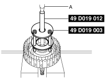
- (3) Press the SSTs down using a press until there is no longer any spring force from the springs and retainer component applied to the snap ring.
-
-
Caution
-
• If the press is pressed excessively, surrounding parts could be damaged.Stop pressing if a gap appears between the snap ring and seal plate.
A :Snap ring
B :Seal plate
C :Gap
- (4) Remove the snap ring from the snap ring groove.
-
- (5) Take the SSTs and part off the press.
-
- (6) Remove the SSTs.
-
- (7) Remove the snap ring removed from the snap ring groove.
-
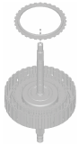
10. Remove the seal plate.
11. Remove the springs and retainer component.
12. Remove the O-ring.
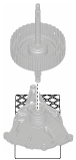
13. Remove the high clutch piston using the following procedure:
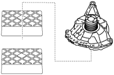
- (1) Set the oil pump on the workbench as shown in the figure.
-
-
Note
-
• Using the rubber plates, adjust the alignment surface of the oil pump with the transaxle case so that it is level.
A :Rubber plate
- (2) Assemble the thrust washer to the drum and shaft component using the following procedure:
-
-
Note
-
• Thrust washer size: Inner diameter approx. 58.7 mm {2.31 in}
- 1) To prevent the thrust washer from dropping out, apply ATF (ATF FZ) to the thrust washer.
- 2) Assemble the thrust washer.
-
- (3) Assemble the parts assembled together in Step (2) to the oil pump.
-
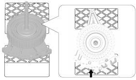
- (4) Blow compressed air into the oil passage shown in the figure.
-
-
Warning
-
• Always wear protective eye wear when using the air compressor. Otherwise, ATF or dirt particles blown off by the air compressor could get into the eyes.
-
Caution
-
• To prevent damage to parts, always use an air compressor which is adjusted to the indicated pressure.
-
Compressed air pressure
-
0.39—0.44 MPa {4.0—4.4 kgf/cm2, 57—63 psi}
- (5) Remove the high clutch piston removed from the drum and shaft component.
-
- (6) Remove the drum and shaft component.
-
- (7) Remove the thrust washer.
-
- (8) Take the oil pump off the rubber plates.
-
14. Clean the disassembled parts. (See AUTOMATIC TRANSAXLE CLEANING.)
15. Perform the following inspection and replace a malfunctioning part with a new one.
-