HIGH CLUTCH CLEARANCE MEASUREMENT/ADJUSTMENT
id051700664600
Preparation Before Servicing
1. Print out the measurement/adjustment value input sheet. (See MEASUREMENT/ADJUSTMENT VALUE INPUT SHEET.)
-
Note
-
• When performing the measurement/adjustment, input the measured and calculated values into the measurement/adjustment value input sheet.
• If the measurement/adjustment value input sheet has already been printed out for the other measurements/adjustments, use the sheet.
High Clutch Clearance Measurement
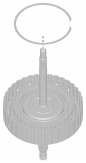
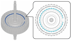
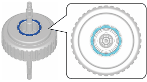
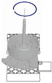
1. Assemble the snap ring.
-
Caution
-
• After assembling the snap ring, verify that the snap ring is securely inserted into the bottom of the snap ring groove.
-
Note
-
• Snap ring size: Outer diameter approx. 122.3 mm {4.815 in}
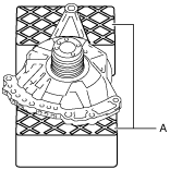
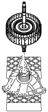
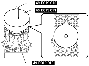
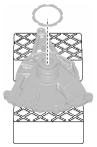
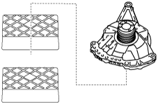
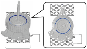
2. Set the oil pump on the workbench as shown in the figure.
-
Caution
-
• To reduce error during the high clutch clearance measurement, use the rubber plates to adjust the alignment surface of the oil pump with the transaxle case so that it is level.
A :Rubber plate
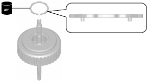
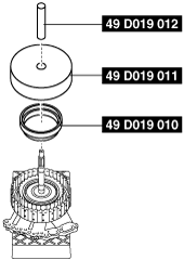
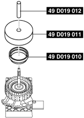
3. Assemble the thrust washer to the clutch component using the following procedure:
-
Note
-
• Thrust washer size: Inner diameter approx. 58.7 mm {2.31 in}
- (1) To prevent the thrust washer from dropping out, apply ATF (ATF FZ) to the thrust washer.
- (2) Assemble the thrust washer.
-
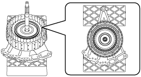
4. Assemble the parts assembled together in Step 3 to the oil pump.
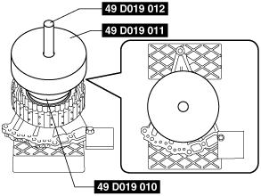
5. Install the SSTs.
-
Caution
-
• Install the SST (49 D019 010) so that the small diameter side is pointing towards the high clutch.
6. Set the measuring instrument to the oil pump using the following procedure:
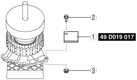
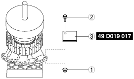
- (1) Install the SST for securing the magnetic stand using the procedure shown in the figure.
-
-
Caution
-
• If the bolt and nut are tightened with excessive force when installing the SST, the alignment surface of the oil pump with the transaxle case could be damaged. Tighten the bolt and nut so that the SST does not move during the high clutch clearance measurement.
-
Note
-
• When installing the SST to the oil pump, use an M8 bolt and nut.
|
1
|
SST (for securing magnetic stand)
|
|
2
|
Bolt (M8)
|
|
3
|
Nut (M8)
|
-
SST installation bolt tightening torque
-
15 N·m {1.5 kgf·m, 11 ft·lbf} or less (tighten so that SST does not move during high clutch clearance measurement)
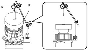
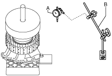
- (2) Set the dial gauge and magnetic stand as shown in the figure.
-
-
Caution
-
• To reduce measurement differences during the high clutch clearance measurement, set the dial gauge so that it is perpendicular to the alignment surface of the oil pump with the transaxle case.
A :Dial gauge
B :Magnetic stand
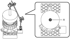
- (3) Set the dial gauge end near the center of the SST.
-
-
Caution
-
• To reduce measurement differences during the high clutch clearance measurement, set the dial gauge end within the area shown in the figure.
A :Dial gauge end set area
7. Measure the high clutch clearance using the following procedure:
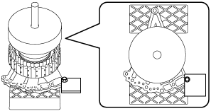
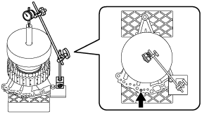
- (1) Blow compressed air into the oil passage shown in the figure to force the high clutch piston to stroke (approx. 3 times).
-
-
Warning
-
• Always wear protective eye wear when using the air compressor. Otherwise, ATF or dirt particles blown off by the air compressor could get into the eyes.
-
Caution
-
• To prevent damage to parts, always use an air compressor which is adjusted to the indicated pressure.
-
Compressed air pressure
-
0.39—0.44 MPa {4.0—4.4 kgf/cm2, 57—63 psi}
- (2) Blow compressed air into the oil passage shown in the figure to operate the high clutch piston, and read the value when the dial gauge is stabilized.
-
-
Warning
-
• Always wear protective eye wear when using the air compressor. Otherwise, ATF or dirt particles blown off by the air compressor could get into the eyes.
-
Caution
-
• To prevent damage to parts, always use an air compressor which is adjusted to the indicated pressure.
• To reduce measurement differences during the high clutch clearance measurement, gently blow and release the compressed air.
-
Compressed air pressure
-
0.39—0.44 MPa {4.0—4.4 kgf/cm2, 57—63 psi}
- (3) Input the dial gauge value, which was read while the high clutch piston was operating, into the measurement/adjustment value input sheet.
- (4) Release the compressed air and read the dial gauge value while the high clutch piston is not operating.
- (5) Input the dial gauge value, which was read while the high clutch piston was not operating, into the measurement/adjustment value input sheet.
- (6) Perform the following calculation to calculate the high clutch clearance.
-
-
High clutch clearance = A - B
-
A: Dial gauge value while high clutch piston is operating
B: Dial gauge value while high clutch piston is not operating
-
Note
-
Example
A: Dial gauge value while high clutch piston is operating is 1.605 mm {0.06319 in}
B: Dial gauge value while high clutch piston is not operating is 0.055 mm {0.0022 in}
High clutch clearance = 1.605 mm {0.06319 in} - 0.055 mm {0.0022 in}= 1.550 mm {0.06102 in}
- (7) Input the calculated high clutch clearance into the measurement/adjustment value input sheet.
- (8) Verify that the high clutch clearance satisfies the specification.
-
-
Specification
-
1.300—1.500 mm {0.05119—0.05905 in}
-
8. Remove the dial gauge and magnetic stand.
A :Dial gauge
B :Magnetic stand
9. Remove the SST for securing the magnetic stand using the procedure shown in the figure.
|
1
|
Nut (M8)
|
|
2
|
Bolt (M8)
|
|
3
|
SST (for securing magnetic stand)
|
10. Remove the SSTs.
11. Remove the clutch component.
12. Remove the thrust washer.
13. Take the oil pump off the rubber plates.
High Clutch Clearance Adjustment
1. Remove the dial gauge and magnetic stand.
A :Dial gauge
B :Magnetic stand
2. Remove the SSTs.
3. Remove the snap ring.
4. Measure the thickness of the removed snap ring.
-
Note
-
• Recommended measuring instrument: Micrometer
5. Input the measured snap ring thickness into the measurement/adjustment value input sheet.
6. Perform the following calculation to calculate the high clutch clearance gap.
-
Note
-
• The high clutch clearance gap is the difference between the high clutch clearance and the median value of the high clutch clearance specification.
-
High clutch clearance gap = C-G
-
C: High clutch clearance
G: High clutch clearance specification median value (1.400 mm {0.05512 in})
-
Note
-
Example
C: High clutch clearance is 1.550 mm {0.06102 in}
High clutch clearance gap = 1.550 mm {0.06102 in} - 1.400 mm {0.05512 in}= 0.15 mm {0.0059 in}
7. Input the calculated high clutch clearance gap into the measurement/adjustment value input sheet.
8. Perform the following calculation to calculate the optimum snap ring thickness.
-
Optimum snap ring thickness = F + H
-
F: Thickness of removed snap ring
H: High clutch clearance gap
-
Note
-
Example
F: Thickness of removed snap ring is 1.615 mm {0.06358 in}
Thickness of optimum snap ring = 1.615 mm {0.06358 in}+0.15 mm {0.0059 in}= 1.765 mm {0.06949 in}
9. Input the calculated optimum snap ring thickness into the measurement/adjustment value input sheet.
10. From the following table, select a snap ring of a thickness closest to the calculated optimum snap ring thickness.
|
Snap ring thickness
|
|
2.1 mm {0.083 in}
|
|
2.0 mm {0.079 in}
|
|
1.9 mm {0.075 in}
|
|
1.8 mm {0.071 in}
|
|
1.7 mm {0.067 in}
|
|
1.6 mm {0.063 in}
|
|
1.5 mm {0.059 in}
|
|
1.4 mm {0.055 in}
|
|
1.3 mm {0.051 in}
|
|
1.2 mm {0.047 in}
|
11. Assemble the selected snap ring.
-
Caution
-
• After assembling the snap ring, verify that the snap ring is securely inserted into the bottom of the snap ring groove.
-
Note
-
• Snap ring size: Outer diameter approx. 122.3 mm {4.815 in}
12. Install the SSTs.
13. Perform the high clutch clearance measurement from Step 6 (2). (See High Clutch Clearance Measurement.)