2-6 BRAKE CLEARANCE MEASUREMENT/ADJUSTMENT


id051700664800


Preparation Before Servicing

1.  Print out the measurement/adjustment value input sheet. (See MEASUREMENT/ADJUSTMENT VALUE INPUT SHEET.)

Note
•  When performing the measurement/adjustment, input the measured and calculated values into the measurement/adjustment value input sheet.
•  If the measurement/adjustment value input sheet has already been printed out for the other measurements/adjustments, use the sheet.


2-6 Brake Clearance Measurement

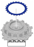
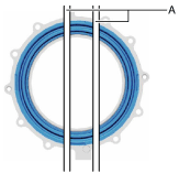
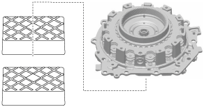
1.  Set the end cover with the assembled part on the workbench as shown in the figure.

Caution
•  To reduce measurement differences during the 2-6 brake clearance measurement, use the rubber plates to adjust the alignment surface of the end cover with the transaxle case so that it is level.
bcw6ja00000716
A  :Rubber plate

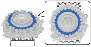
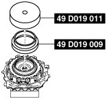
2.  Assemble the retaining plate.

Note
•  Retaining plate size: Inner diameter approx. 137.2 mm {5.402 in}
bcw6ja00000717
bcw6ja00000718

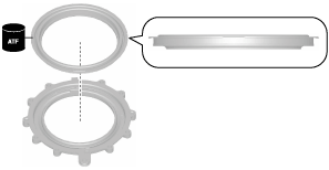
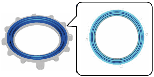
3.  Assemble the 2-6 brake piston to the brake housing using the following procedure:

(1)  Apply ATF (ATF FZ) to the 2-6 brake piston lip.
(2)  Assemble the 2-6 brake piston.
bcw6ja00000472
bcw6ja00000473

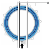
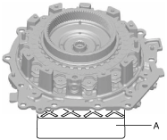
4.  Measure distance A shown in the figure of the assembled parts from Step 3 and calculate the average value of distance A.

Note
•  Recommended measuring instrument: Depth micrometer, straight edge ruler
bcw6ja00000726
A  :Distance A
B  :2-6 brake piston end
C  :Brake housing end (alignment surface with end cover)
(1)  Measure the thickness of the straight edge ruler.
Note
•  Recommended measuring instrument: Micrometer
(2)  Input the measured straight edge ruler thickness into the measurement/adjustment value input sheet.
(3)  Set two straight edge rulers on the 2-6 brake piston as shown in the figure.
bcw6ja00000981
A  :Straight edge ruler
(4)  Measure the positions in 3 locations (each separated by 120°) shown in the figure and subtract the thickness of the straight edge ruler from distance A.
bcw6ja00000720
A  :Straight edge ruler
(5)  Input distance A and the average value of distance A into the measurement/adjustment value input sheet.

5.  Install the SSTs.

Caution
•  Install the SST (49 D019 009) so that the end with the large diameter is pointing towards the retaining plate.
bcw6ja00000624
bcw6ja00000625

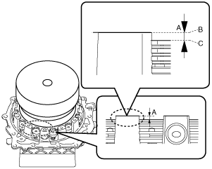
6.  Measure distance B shown in the figure at the four locations (each separated by 120°) and calculate the average value of distance B.

Note
•  Recommended measuring instrument: Depth micrometer
•  Measure the splines of the retaining plate using a depth micrometer.
bcw6ja00000626
A  :Distance B
B  :End cover end (alignment surface with brake housing)
C  :Retaining plate end

7.  Input the measured distance B and calculated distance B average value into the measurement/adjustment value input sheet.

8.  Perform the following calculation to calculate the 2-6 brake clearance.

2-6 Brake Clearance = E - C
C: Average value of distance A
E: Average value of distance B
Note
Example
C: Average value of distance A is 3.150 mm {0.1240 in}
E: Average value of distance B is 4.370 mm {0.1720 in}
2-6 brake clearance = 4.370 mm {0.1720 in} - 3.150 mm {0.1240 in}= 1.220 mm {0.04803 in}

9.  Input the calculated 2-6 brake clearance into the measurement/adjustment value input sheet.

10.  Verify that the 2-6 brake clearance satisfies the specification.

Specification
1.000—1.200 mm {0.03938—0.04724 in}
•  If not within the specification, adjust the 2-6 brake clearance. (See 2-6 Brake Clearance Adjustment.)

11.  Remove the SSTs.

bcw6ja00000624

12.  Take the end cover off the rubber plates.

bcw6ja00000721


2-6 Brake Clearance Adjustment

1.  Remove the SSTs.

bcw6ja00000624

2.  Remove the retaining plate.

bcw6ja00000717

3.  Measure the thickness of the removed retaining plate.

Note
•  Recommended measuring instrument: Micrometer

4.  Input the measured retaining plate thickness into the measurement/adjustment value input sheet.

5.  Perform the following calculation to calculate the 2-6 brake clearance gap.

Note
•  The 2-6 brake clearance gap is the difference between the 2-6 brake clearance and the median value of the 2-6 brake clearance specification.
2-6 brake clearance gap = F-J
F: 2-6 brake clearance
J: 2-6 brake clearance specification median value (1.100 mm {0.04331 in})
Note
Example
F: 2-6 brake clearance is 1.220 mm {0.04803 in}
2-6 brake clearance gap = 1.220 mm {0.04803 in} - 1.100 mm {0.04331 in}= 0.120 mm {0.00472 in}

6.  Input the calculated 2-6 brake clearance gap into the measurement/adjustment value input sheet.

7.  Perform the following calculation to calculate the optimum retaining plate thickness.

Thickness of optimum retaining plate = I + K
I: Thickness of removed retaining plate
K: 2-6 brake clearance gap
Note
Example
I: Thickness of removed retaining plate is 1.615 mm {0.06358 in}
Thickness of optimum retaining plate = 1.615 mm {0.06358 in}+ 0.120 mm {0.00472 in}= 1.735 mm {0.06831 in}

8.  Input the calculated optimum retaining plate thickness into the measurement/adjustment value input sheet.

9.  From the following table, select a retaining plate of a thickness closest to the calculated optimum thrust retaining plate.

Retaining plate thickness

2.2 mm {0.087 in}
2.1 mm {0.083 in}
2.0 mm {0.079 in}
1.9 mm {0.075 in}
1.8 mm {0.071 in}
1.7 mm {0.067 in}
1.6 mm {0.063 in}

10.  Assemble the selected retaining plate.

bcw6ja00000717
bcw6ja00000718

11.  Perform the 2-6 brake clearance measurement from Step 5. (See 2-6 Brake Clearance Measurement.)