RING GEAR AND DIFFERENTIAL PRELOAD MEASUREMENT/ADJUSTMENT
id051700665100
Preparation Before Servicing
1. Print out the measurement/adjustment value input sheet. (See MEASUREMENT/ADJUSTMENT VALUE INPUT SHEET.)
-
Note
-
• When performing the measurement/adjustment, input the measured and calculated values into the measurement/adjustment value input sheet.
• If the measurement/adjustment value input sheet has already been printed out for the other measurements/adjustments, use the sheet.
Ring Gear and Differential Preload Measurement
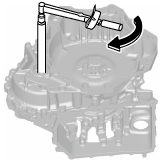
1. Rotate and adjust the rotation handle of the engine stand so that the converter housing side is facing upward.
2. Remove any remaining old sealant on the contact surfaces of the transaxle case and converter housing.
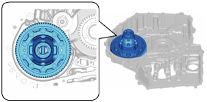
3. Assemble the ring gear and differential using the following procedure.
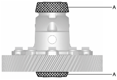
- (1) Apply ATF (ATF FZ) to the roller area of the tapered roller bearing of the ring gear and differential.
-
-
Caution
-
• Accurately perform the procedure to reduce the error on the ring gear and differential preload measurement.
A :ATF application area
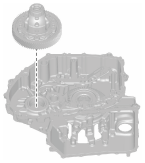
- (2) Assemble the ring gear and differential.
-
4. Assemble the bearing race and a new shim with the same thickness as the removed shim to the converter housing using the following procedure:
-
Caution
-
• Always use a new shim. If a deformed shim is reused, it may cause a transaxle malfunction.
- (1) Apply ATF (ATF FZ) to the engagement area of the bearing race and converter housing.
-
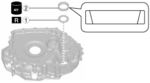
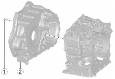
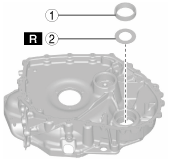
- (2) Assemble the bearing race and a new shim with the same thickness as the removed shim using the following procedure and the SSTs:
-
|
1
|
Shim (outer diameter approx. 67.4 mm {2.65 in})
(new shim with same thickness of removed shim)
|
|
2
|
Bearing race (outer diameter approx. 68 mm {2.7 in})
|
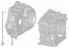
5. Assemble the converter housing using the following procedure:
|
1
|
Converter housing
|
|
2
|
21 bolts (M8 x 1.25 bolt, length approx. 28 mm {1.1 in})
|
- (1) Assemble the converter housing.
-
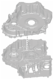
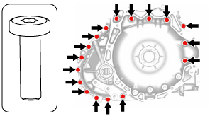
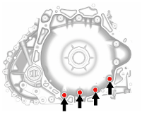
- (2) Assemble and temporarily tighten the bolts to the positions shown in the figure.
-
-
Note
-
• Bolt size: M8 x 1.25 bolt (length approx. 28 mm {1.1 in})
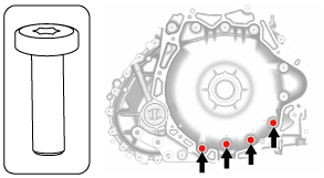
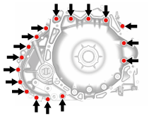
- (3) Assemble and temporarily tighten the bolts to the positions shown in the figure.
-
-
Caution
-
• When performing the automatic transaxle assembly after the ring gear and differential preload measurement/adjustment, use new bolts, otherwise ATF leakage could occur.
-
Note
-
• The bolts for the assembly are applied with sealant. However, the bolts are reused for removal after the ring gear and differential preload measurement/adjustment.
• Bolt size: M8 x 1.25 bolt (length approx. 28 mm {1.1 in})
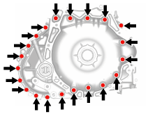
- (4) Tighten the bolts shown in the figure.
-
-
Tightening torque
-
19—25 N·m {2.0—2.5 kgf·m, 15—18 ft·lbf}
6. Measure the ring gear and differential preload using the following procedure.
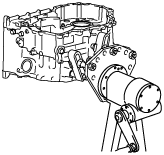
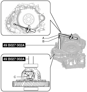
- (1) Set the SST, torque wrench, and socket (14 mm {0.55 in}) as shown in the figure.
-
-
Note
-
• Engage the groove on the end of the SST with the pinion shaft.
A :Torque wrench
B :Socket (14 mm {0.55 in})
A :Torque wrench
B :Socket (14 mm {0.55 in})
C :Pinion shaft
- (2) Rotate the ring gear and differential in the direction of the arrow shown in the figure using a torque wrench and measure the ring gear and differential preload.
-
-
Caution
-
• Measure the ring gear and differential preload after rotating the ring gear and differential approx. 10 times in the direction of the arrow shown in the figure to engage the tapered roller bearing.
• As a ring gear and differential preload, measure the rotational torque when the ring gear and differential is rotated at approx. 20 rpm (speed of one rotation for 3 s).
- (3) Input the measured ring gear and differential preload into the measurement/adjustment value input sheet.
-
- (4) Verify that the ring gear and differential preload satisfies the specification.
-
-
Specification
-
0.83 — 1.51 N·m {8.5—15 kgf·cm, 7.3—13 in·lbf}
-
- (5) Remove the SST, torque wrench, and socket (14 mm {0.55 in}).
-
A :Torque wrench
B :Socket (14 mm {0.55 in})
7. Remove the converter housing using the following procedure:
|
1
|
21 bolts
|
|
2
|
Converter housing
|
- (1) Remove the bolts shown in the figure.
-
-
Caution
-
• Sealant has been applied to the removed bolts. If the bolts are reused it could cause ATF leakage, therefore when performing the automatic transaxle assembly, use new bolts.
- (2) Remove the bolts shown in the figure.
-
- (3) Remove the converter housing.
-
8. Remove the ring gear and differential.
Ring Gear and Differential Preload Adjustment
1. Remove the SST, torque wrench, and socket (14 mm {0.55 in}).
A :Torque wrench
B :Socket (14 mm {0.55 in})
2. Remove the converter housing using the following procedure:
|
1
|
24 bolts
|
|
2
|
Converter housing
|
- (1) Remove the bolts shown in the figure.
-
-
Caution
-
• Sealant has been applied to the removed bolts. If the bolts are reused it could cause ATF leakage, therefore when performing the automatic transaxle assembly, use new bolts.
- (2) Remove the bolts shown in the figure.
-
- (3) Remove the converter housing.
-
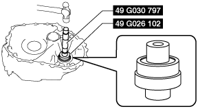
3. Remove the bearing race and shim from the converter housing using the SST and procedure shown in the figure.
-
Caution
-
• Because the shim will deform when removing the bearing race, use a new shim when performing the shim assembly.
4. Measure the thickness of the removed shim.
-
Note
-
• Recommended measuring instrument: Micrometer
5. Input the measured shim thickness into the measurement/adjustment value input sheet.
6. Perform the following calculation to calculate the preload gap.
-
Note
-
• The preload gap is the difference between the ring gear and differential preload and the median value of the ring gear and differential preload specification.
-
Preload gap = E−A
-
A: Ring gear and differential preload
E: Median value of ring gear and differential preload specification (1.17 N·m {12 kgf·cm, 11 in·lbf})
-
Note
-
Example
A: Ring gear and differential preload is 0.70 N·m {7.1 kgf·cm, 6.2 in·lbf}
Preload gap = 1.17 N·m {12 kgf·cm, 11 in·lbf} - 0.70 N·m {7.1 kgf·cm, 6.2 in·lbf}= 0.47 N·m {4.8 kgf·cm, 4.2 in·lbf}
7. Input the calculated preload gap into the measurement/adjustment value input sheet.
8. Perform the following calculation to calculate the shim thickness gap.
-
Note
-
• The shim thickness gap is the difference between the removed shim thickness and the optimum shim thickness.
• If the shim thickness is thickened 0.1 mm {0.004 in}, the ring gear and differential preload increases approx. 0.75 N·m {7.6 kgf·cm, 6.6 in·lbf}.
-
Shim thickness gap = F × 0.1 mm {0.004 in}/ 0.75 N·m {7.6 kgf·cm, 6.6 in·lbf}
-
F: Preload gap
-
Note
-
Example
F: Preload gap is 0.47 N·m {4.8 kgf·cm, 4.2 in·lbf}
Shim thickness gap = 0.47 N·m {4.8 kgf·cm, 4.2 in·lbf}× 0.1 mm {0.004 in}/ 0.75 N·m {7.6 kgf·cm, 6.6 in·lbf}= 0.063 mm {0.0025 in}
9. Input the calculated shim thickness gap into the measurement/adjustment value input sheet.
10. Perform the following calculation to calculate the optimum shim thickness.
-
Optimum shim thickness = D + G
-
D: Thickness of removed shim
G: Shim thickness gap
-
Note
-
Example
D: Thickness of removed shim is 0.905 mm {0.0356 in}
G: Shim thickness gap is 0.063 mm {0.0025 in}
Thickness of optimum shim = 0.905 mm {0.0356 in}+ 0.063 mm {0.0025 in}= 0.968 mm {0.0381 in}
11. Input the calculated optimum shim thickness into the measurement/adjustment value input sheet.
12. From the following table, select a new shim of a thickness nearest to the calculated optimum thickness
|
Shim thickness
|
|
1.45 mm {0.0571 in}
|
|
1.40 mm {0.0551 in}
|
|
1.35 mm {0.0531 in}
|
|
1.30 mm {0.0512 in}
|
|
1.25 mm {0.0492 in}
|
|
1.20 mm {0.0472 in}
|
|
1.15 mm {0.0453 in}
|
|
1.10 mm {0.0433 in}
|
|
1.05 mm {0.0413 in}
|
|
1.00 mm {0.0394 in}
|
|
0.95 mm {0.037 in}
|
|
0.90 mm {0.035 in}
|
|
0.85 mm {0.033 in}
|
|
0.80 mm {0.031 in}
|
|
0.75 mm {0.030 in}
|
|
0.70 mm {0.028 in}
|
|
0.65 mm {0.026 in}
|
|
0.60 mm {0.024 in}
|
|
0.55 mm {0.022 in}
|
|
0.50 mm {0.020 in}
|
13. Assemble the bearing race and selected new shim to the converter housing using the following procedure:
-
Caution
-
• Always use a new shim. If a deformed shim is reused, it may cause a transaxle malfunction.
- (1) Apply ATF (ATF FZ) to the engagement area of the bearing race and converter housing.
-
- (2) Assemble the bearing race and selected new shim using the following procedure and SST:
-
|
1
|
Shim (outer diameter approx. 67.4 mm {2.65 in})
(selected new shim)
|
|
2
|
Bearing race (outer diameter approx. 68 mm {2.7 in})
|
14. Perform ring gear and differential preload measurement from Step 5. (See Ring Gear and Differential Preload Measurement.)