LOW AND REVERSE BRAKE (PISTON B1) CLEARANCE MEASUREMENT/ADJUSTMENT
id051700681000
Preparation Before Servicing
1. Print out the measurement/adjustment value input sheet. (See MEASUREMENT/ADJUSTMENT VALUE INPUT SHEET.)
-
Note
-
• When performing the measurement/adjustment, input the measured and calculated values into the measurement/adjustment value input sheet.
• If the measurement/adjustment value input sheet has already been printed out for the other measurements/adjustments, use the sheet.
Low and Reverse Brake (Piston B) Clearance Measurement
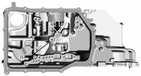
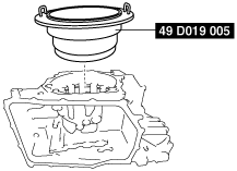
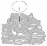
1. Set the case so that the end cover side is facing upward.
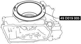
2. Assemble the snap ring using the following procedure:
-
Note
-
• Snap ring size: Outer diameter approx. 180.5 mm {7.106 in}
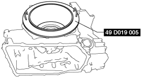
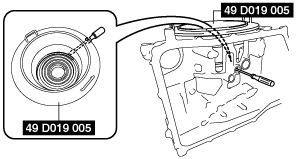
- (1) Install the SST.
-
- (2) Install the SST to the snap ring.
-
A :Snap ring
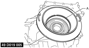
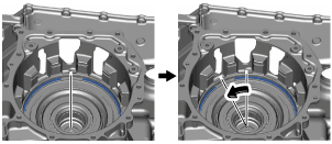
- (3) Rotate the SST and adjust the snap ring end gap to the oil passage part shown in the figure.
-
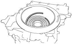
- (4) Assemble the snap ring.
- (5) Remove the SST.
-
-
Note
-
• Because the gap between the SST and part is small, remove the SST from directly above.
- (6) Verify that the snap ring end gap is assembled to the position shown in the figure.
-
3. Set the measuring instrument to the transaxle case using the following procedure.
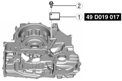
- (1) Install the SST for securing the magnetic stand using the procedure shown in the figure.
-
-
Caution
-
• If the bolt is tightened with excessive force when installing the SST, the alignment surface of the end cover with the transaxle case could be damaged. Tighten the bolt so that the SST does not move during low and reverse brake (piston B1) clearance measurement.
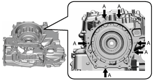
• To prevent damage to the parts, the bolt holes in the transaxle case which are used for securing the SST are the penetrated bolt holes shown in the figure.
-
Note
-
• When installing the SST to the transaxle case, use a bolt (M8 × 1.25).
• Use a bolt length in which the bolt end comes out of the transaxle case bolt hole but does not contact the transaxle case.
• Because it is necessary to measure the low and reverse brake (piston B1) clearance at four locations (each separated by 90°), change the SST installation position to the area of the bolt installation position shown in the figure and install the SST to a position which facilitates measurement.
A :Bolt installation positions for SST installation
|
1
|
SST (for securing magnetic stand)
|
|
2
|
Bolt (M8 × 1.25)*
|
* :Use a bolt length in which the bolt end comes out of the transaxle case bolt hole but does not contact the transaxle case.
-
SST installation bolt tightening torque
-
15 N·m {1.5 kgf·m, 11 ft·lbf} or less (tighten so that SST does not move during low and reverse brake (piston B1) clearance measurement)
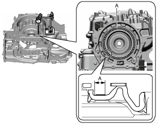
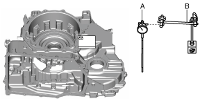
- (2) Set the dial gauge and magnetic stand as shown in the figure.
-
-
Caution
-
• To reduce measurement differences during the low and reverse brake (piston B1) clearance measurement, set the dial gauge so that it is perpendicular to the alignment surface of the transaxle case with the end cover.
A :Dial gauge
B :Magnetic stand
- (3) Set the dial gauge end to low and reverse brake piston B1.
-
-
Note
-
• Measure the stroke amount of low and reverse brake piston B1 as the low and reverse brake (piston B1) clearance.
A :Dial gauge end set area
4. Measure the low and reverse brake (piston B1) clearance using the following procedure:
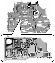
- (1) Blow compressed air into the oil passage shown in the figure to force low and reverse brake piston B1 to stroke (approx. 3 times).
-
-
Warning
-
• Always wear protective eye wear when using the air compressor. Otherwise, ATF or dirt particles blown off by the air compressor could get into the eyes.
-
Caution
-
• To prevent damage to parts, always use an air compressor which is adjusted to the indicated pressure.
-
Compressed air pressure
-
0.39—0.44 MPa {4.0—4.4 kgf/cm2, 57—63 psi}
- (2) Blow compressed air into the oil passage shown in the figure to operate low and reverse brake piston B1, and read the value when the dial gauge is stabilized.
-
-
Warning
-
• Always wear protective eye wear when using the air compressor. Otherwise, ATF or dirt particles blown off by the air compressor could get into the eyes.
-
Caution
-
• To prevent damage to parts, always use an air compressor which is adjusted to the indicated pressure.
• To reduce measurement differences during the low and reverse brake (piston B1) clearance, gently blow and release compressed air.
-
Compressed air pressure
-
0.39—0.44 MPa {4.0—4.4 kgf/cm2, 57—63 psi}
- (3) Input the dial gauge value, which was read while low and reverse brake piston B1 was operating, into the measurement/adjustment value input sheet.
- (4) Release the compressed air and read the dial gauge value while low and reverse brake piston B1 is not operating.
- (5) Input the dial gauge value, which was read while low and reverse brake piston B1 was not operating, into the measurement/adjustment value input sheet.
- (6) Perform the following calculation to calculate the low and reverse brake (piston B1) clearance.
-
-
Low and reverse brake (piston B1) clearance = A - B
-
A: Dial gauge value while low and reverse brake piston B1 is operating
B: Dial gauge value while low and reverse brake piston B1 is not operating
-
Note
-
Example
A: Dial gauge value while low and reverse brake piston B1 is operating is 2.470 mm {0.09724 in}
B: Dial gauge value while low and reverse brake piston B1 is not operating is 0.595 mm {0.0234 in}
Low and reverse brake (piston B1) clearance = 2.470 mm {0.09724 in}− 0.595 mm {0.0234 in}= 1.875 mm {0.07382 in}
- (7) Input the calculated low and reverse brake (piston B1) clearance into the measurement/adjustment value input sheet.
- (8) Measure the low and reverse brake (piston B1) clearance at the four locations (each separated by 90°) and calculate the average value of the low and reverse brake (piston B1) clearance.
-
-
Note
-
• Change the set positions of the dial gauge and magnetic stand and measure the low and reverse brake (piston B1) clearance at the four locations (each separated by 90°).
- (9) Input the calculated average value of the low and reverse brake (piston B1) clearance into the measurement/adjustment value input sheet.
- (10) Verify that the average value of the low and reverse brake (piston B1) clearance satisfies the specification.
-
-
Specification
-
1.500—1.700 mm {0.05906—0.06692 in}
-
5. Remove the dial gauge and magnetic stand.
A :Dial gauge
B :Magnetic stand
6. Remove the SST for securing the magnetic stand using the procedure shown in the figure.
|
1
|
Bolt
|
|
2
|
SST (for securing magnetic stand)
|
Low and Reverse Brake (Piston B1) Clearance Adjustment
1. Remove the dial gauge and magnetic stand.
A :Dial gauge
B :Magnetic stand
2. Remove the SST for securing the magnetic stand using the procedure shown in the figure.
|
1
|
Bolt
|
|
2
|
SST (for securing magnetic stand)
|
3. Remove the snap ring using the following procedure:
- (1) Move the snap ring end gap position.
-
-
Caution
-
• Do not damage the piston sliding surface. Otherwise, hydraulic pressure may leak.
- (2) Install the SST.
-
- (3) Insert a small screwdriver into the oil passage and press the snap ring.
-
- (4) Remove the snap ring.
-
4. Measure the thickness of the removed snap ring.
-
Note
-
• Recommended measuring instrument: Micrometer
5. Input the measured snap ring thickness into the measurement/adjustment value input sheet.
6. Perform the following calculation to calculate the low and reverse brake (piston B1) clearance gap.
-
Note
-
• The low and reverse brake (piston B1) clearance gap is the difference between the average value of the low and reverse brake (piston B1) clearance and the median value of the low and reverse brake (piston B1) clearance specification.
-
Low and reverse brake (piston B1) clearance gap = D-H
-
D: Low and reverse brake (piston B1) clearance average value
H: Median value of low and reverse brake (piston B1) clearance specification (1.600 mm {0.06299 in})
-
Note
-
Example
D: Average value of low and reverse brake (piston B1) clearance is 1.875 mm {0.07382 in}
Low and reverse brake (piston B1) clearance gap = 1.875 mm {0.07382 in} - 1.600 mm {0.06299 in}= 0.275 mm {0.0108 in}
7. Input the calculated low and reverse brake (piston B1) clearance gap into the measurement/adjustment value input sheet.
8. Perform the following calculation to calculate the optimum snap ring thickness.
-
Optimum snap ring thickness = G + I
-
G: Thickness of removed snap ring
I: low and reverse brake (piston B1) clearance gap
-
Note
-
Example
G: Thickness of removed snap ring is 2.125 mm {0.08366 in}
Thickness of optimum snap ring = 2.125 mm {0.08366 in}+ 0.275 mm {0.0108 in}= 2.400 mm {0.09449 in}
9. Input the calculated optimum snap ring thickness into the measurement/adjustment value input sheet.
10. From the following table, select a snap ring of a thickness closest to the calculated optimum snap ring thickness.
|
Snap ring thickness
|
|
2.8 mm {0.11 in}
|
|
2.7 mm {0.11 in}
|
|
2.6 mm {0.10 in}
|
|
2.5 mm {0.098 in}
|
|
2.4 mm {0.094 in}
|
|
2.3 mm {0.091 in}
|
|
2.2 mm {0.087 in}
|
|
2.1 mm {0.083 in}
|
|
2.0 mm {0.079 in}
|
|
1.9 mm {0.075 in}
|
|
1.8 mm {0.071 in}
|
11. Assemble the selected snap ring using the following procedure:
-
Note
-
• Snap ring size: Outer diameter approx. 180.5 mm {7.106 in}
- (1) Install the SST to the selected snap ring.
-
A :Snap ring
- (2) Rotate the SST and adjust the snap ring end gap to the oil passage part shown in the figure.
-
- (3) Assemble the snap ring.
- (4) Remove the SST.
-
-
Note
-
• Because the gap between the SST and part is small, remove the SST from directly above.
- (5) Verify that the snap ring end gap is assembled to the position shown in the figure.
-
12. Perform the low and reverse brake (piston B1) clearance measurement from step 3. (See Low and Reverse Brake (Piston B) Clearance Measurement.)