 |
bf62zm00000173
TRANSAXLE ASSEMBLY
id051500170000
Step 1
1. Perform the shim adjustment and select a shim of the appropriate thickness. (See SHIM ADJUSTMENT.)
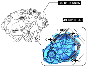
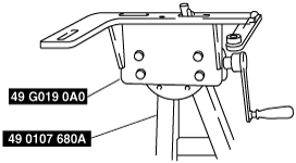
2. Assemble the SST (49 G019 0A0) to the SST (49 0107 680A).
bf62zm00000173
|
3. Assemble the clutch housing component to the SST (49 G019 0A0).
bf62zm00000174
|
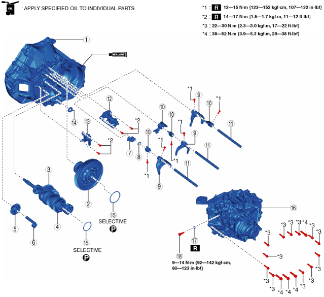
4. Assemble the transaxle in the order shown in the figure.
bf62zm00000175
|
|
1
|
Clutch housing component
|
|
2
|
Differential
|
|
3
|
Secondary shaft component
|
|
4
|
Primary shaft component
|
|
5
|
Reverse idler gear
|
|
6
|
Reverse idler shaft
|
|
7
|
Reverse gate
|
|
8
|
Spring
|
|
9
|
Shift fork
|
|
10
|
Shift rod end
|
|
11
|
Shift rod
|
|
12
|
Control set
|
|
13
|
Reverse lever component
|
|
14
|
Magnet
|
|
15
|
Shim
|
|
16
|
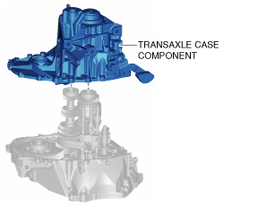
Transaxle case component
|
|
17
|
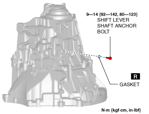
Gasket
|
|
18
|
Shift lever shaft anchor bolt
|
Secondary shaft component and primary shaft component assembly note
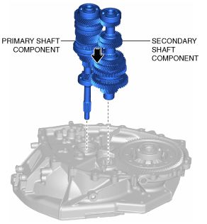
1. Assemble the secondary shaft component and primary shaft component to the clutch housing component as a single unit.
bf62zm00000176
|
2. Shake the assembled parts and assemble each one completely.
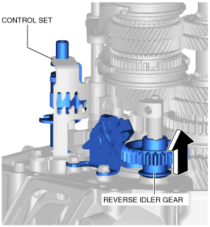
Reverse idler shaft assembly note
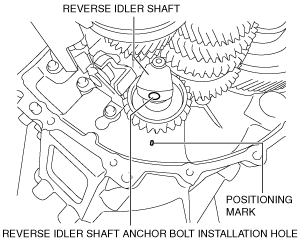
1. Align the reverse idler shaft anchor bolt installation hole of the reverse idler shaft with the positioning mark of the clutch housing, and assemble the reverse idler shaft as shown in the figure.
bf62zm00000177
|
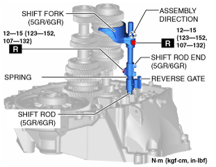
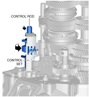
Shift fork, shift rod end, shift rod, spring, and reverse gate assembly note
1. Assemble the shift fork (5GR/6GR), shift rod end (5GR/6GR), shift rod (5GR/6GR), spring, and reverse gate using the following procedure:
bf62zm00000178
|
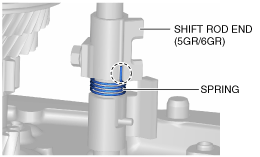
Shift rod end side
bf62zm00000179
|
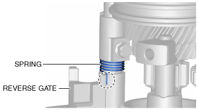
Reverse gate side
bf62zm00000180
|
2. Assemble the shift fork (3GR/4GR), shift rod end (3GR/4GR), shift rod end (reverse), and shift rod (3GR/4GR) using the following procedure:
bf62zm00000181
|
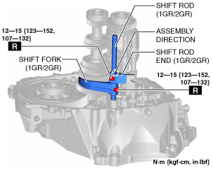
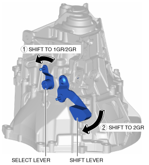
3. Assemble the shift fork (1GR/2GR), shift rod end (1GR/2GR), and shift rod (1GR/2GR) using the following procedure:
bf62zm00000182
|
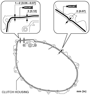
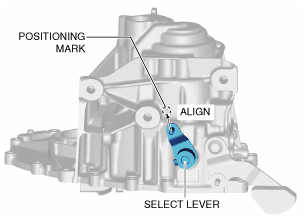
Transaxle case component assembly note
1. Apply silicone sealant TB1216B or equivalent to the clutch housing as shown in the figure.
bf62zm00000183
|
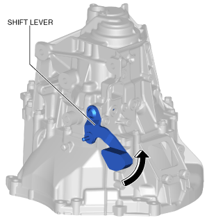
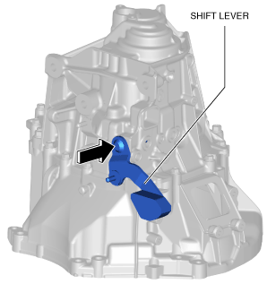
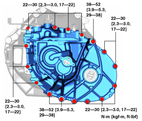
2. Assemble the transaxle case component using the following procedure:
bf62zm00000184
|
bf62zm00000185
|
bf62zm00000186
|
bf62zm00000187
|
bf62zm00000188
|
bf62zm00000189
|
bf62zm00000190
|
bf62zm00000191
|
bf62zm00000192
|
bf62zm00000193
|
bf62zm00000194
|
Step 2
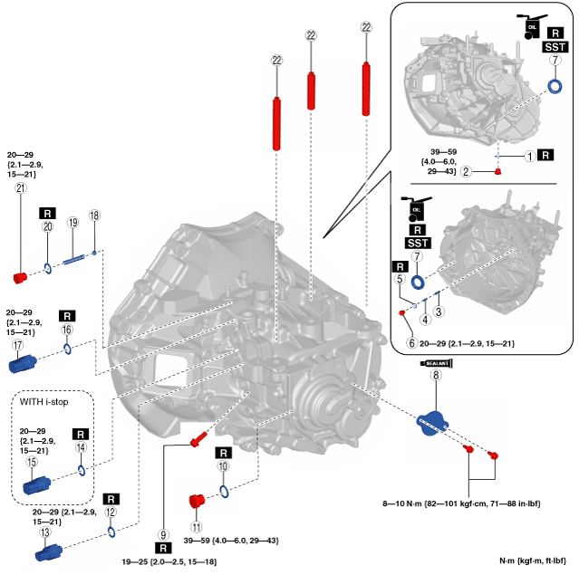
1. Assemble the parts around the transaxle in the order shown in the figure.
bf62zm00000146
|
|
1
|
Gasket
|
|
2
|
Drain plug
|
|
3
|
Pin
|
|
4
|
Spring
|
|
5
|
Gasket
|
|
6
|
Plug
|
|
7
|
Oil seal
(See Oil seal assembly note.)
|
|
8
|
Service hole plate
|
|
9
|
Reverse idler shaft anchor bolt
|
|
10
|
Gasket
|
|
11
|
Oil level plug
|
|
12
|
Gasket
|
|
13
|
Back-up light switch
|
|
14
|
Gasket (with i-stop)
|
|
15
|
Neutral switch No.2 (with i-stop)
|
|
16
|
Gasket
|
|
17
|
Neutral switch No.1
|
|
18
|
Detent ball
|
|
19
|
Spring
|
|
20
|
Gasket
|
|
21
|
Plug
|
|
22
|
Stud bolt
(See Stud bolt assembly note.)
|
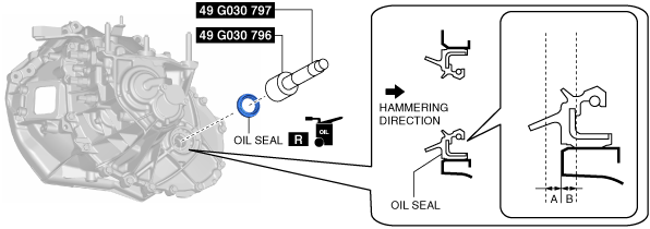
Oil seal assembly note
1. Assemble a new oil seal (LH) to the transaxle case using the SSTs.
bf62zm00000195
|
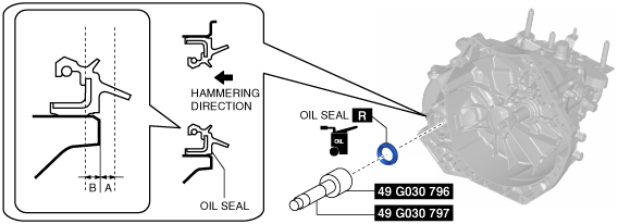
2. Assemble a new oil seal (RH) to the clutch housing using the SSTs.
bf62zm00000196
|
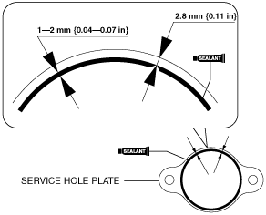
Service hole plate assembly note
1. Verify that there is no damage on the service hole plate installation surface.
2. Apply silicone sealant TB1216B or equivalent to the service hole plate as shown in the figure.
bf62zm00000197
|
3. Assemble the service hole plate.
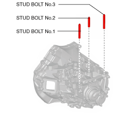
Stud bolt assembly note
1. Assemble the stud bolts.
bf62zm00000198
|
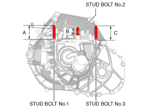
2. Measure the projection of the stud bolts.
bf62zm00000199
|