AUXILIARY JACK/USB PORT INSPECTION
id092000811600
Auxiliary Jack Inspection
1. Disconnect the negative battery cable. (See NEGATIVE BATTERY CABLE DISCONNECTION/CONNECTION.)
2. Remove the following parts:
- (1) Center console tray (See CENTER CONSOLE TRAY REMOVAL/INSTALLATION.)
- (2) Shift bezel (See SHIFT BEZEL REMOVAL/INSTALLATION.)
- (3) Upper panel (See UPPER PANEL REMOVAL/INSTALLATION.)
- (4) Selector lever knob (ATX) (See AUTOMATIC TRANSAXLE SHIFT MECHANISM REMOVAL/INSTALLATION.)
- (5) Shift panel (See SHIFT PANEL REMOVAL/INSTALLATION.)
- (6) Console side panel (See CONSOLE SIDE PANEL REMOVAL/INSTALLATION.)
- (7) Front console box (See FRONT CONSOLE BOX REMOVAL/INSTALLATION.)
- (8) CD player (with CD player) (See CD PLAYER REMOVAL.) (See CD PLAYER INSTALLATION.)
- (9) Front console (See FRONT CONSOLE REMOVAL/INSTALLATION.)
- (10) Auxiliary jack/USB port (See AUXILIARY JACK/USB PORT REMOVAL/INSTALLATION.)
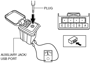
3. Connect a commercially-available plug to the auxiliary jack/USB port.
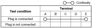
4. Verify that the continuity between the auxiliary jack/USB port terminals is as indicated in the table.
-
USB Port Inspection
1. Disconnect the negative battery cable. (See NEGATIVE BATTERY CABLE DISCONNECTION/CONNECTION.)
2. Remove the following parts:
- (1) Center console tray (See CENTER CONSOLE TRAY REMOVAL/INSTALLATION.)
- (2) Shift bezel (See SHIFT BEZEL REMOVAL/INSTALLATION.)
- (3) Upper panel (See UPPER PANEL REMOVAL/INSTALLATION.)
- (4) Selector lever knob (ATX) (See AUTOMATIC TRANSAXLE SHIFT MECHANISM REMOVAL/INSTALLATION.)
- (5) Shift panel (See SHIFT PANEL REMOVAL/INSTALLATION.)
- (6) Console side panel (See CONSOLE SIDE PANEL REMOVAL/INSTALLATION.)
- (7) Front console box (See FRONT CONSOLE BOX REMOVAL/INSTALLATION.)
- (8) CD player (with CD player) (See CD PLAYER REMOVAL.) (See CD PLAYER INSTALLATION.)
- (9) Front console (See FRONT CONSOLE REMOVAL/INSTALLATION.)
- (10) Auxiliary jack/USB port (See AUXILIARY JACK/USB PORT REMOVAL/INSTALLATION.)
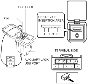
3. Insert the pins to positions A', B', C', and D' shown in the figure from the side of the USB device insertion area for the auxiliary jack/USB port, and verify the continuity at the insertion side and terminal side of the USB device.
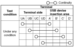
4. Verify that the continuity at the insertion side and terminal side of the USB device is as indicated in the table.
-
Note
-
• When inspecting the USB device insertion side, touch it with a paper clip or similar thin pin without directly inserting a tester into the terminals.
-