PARKING SENSOR SWITCH INSPECTION
id092200042700
-
Note
-
• The parking sensor switch is integrated with the cluster switch.
Continuity Inspection
1. Disconnect the negative battery cable. (See NEGATIVE BATTERY CABLE DISCONNECTION/CONNECTION.)
2. Remove the following parts:
- (1) Driver-side front scuff plate (See FRONT SCUFF PLATE REMOVAL/INSTALLATION.)
- (2) Driver-side front side trim (See FRONT SIDE TRIM REMOVAL/INSTALLATION.)
- (3) Bonnet release lever (See BONNET RELEASE LEVER AND RELEASE CABLE REMOVAL/INSTALLATION.)
- (4) Fuel-filler lid opener lever (See FUEL-FILLER LID OPENER AND LEVER REMOVAL/INSTALLATION.)
- (5) Driver-side lower panel (See DRIVER-SIDE LOWER PANEL REMOVAL/INSTALLATION.)
- (6) Cluster switch (See CLUSTER SWITCH REMOVAL/INSTALLATION.)
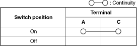
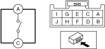
3. Verify that the continuity between the cluster switch terminals is as indicated in the table.
-
LED Illumination Inspection
1. Disconnect the negative battery cable. (See NEGATIVE BATTERY CABLE DISCONNECTION/CONNECTION.)
2. Remove the following parts:
- (1) Driver-side front scuff plate (See FRONT SCUFF PLATE REMOVAL/INSTALLATION.)
- (2) Driver-side front side trim (See FRONT SIDE TRIM REMOVAL/INSTALLATION.)
- (3) Bonnet release lever (See BONNET RELEASE LEVER AND RELEASE CABLE REMOVAL/INSTALLATION.)
- (4) Fuel-filler lid opener lever (See FUEL-FILLER LID OPENER AND LEVER REMOVAL/INSTALLATION.)
- (5) Driver-side lower panel (See DRIVER-SIDE LOWER PANEL REMOVAL/INSTALLATION.)
- (6) Cluster switch (See CLUSTER SWITCH REMOVAL/INSTALLATION.)
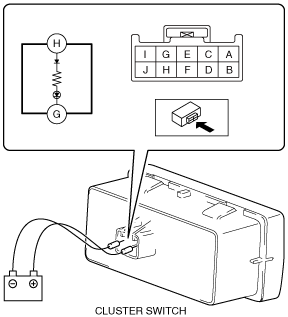
3. Apply battery voltage to cluster switch terminal H, and connect terminal G to ground.
4. Verify that the LED is turned on.
-