VEHICLE SPEED SENSOR (VSS) INSPECTION [FN4A-EL]
id0517a1801400
Visual Inspection
1. Remove the VSS. (See VEHICLE SPEED SENSOR (VSS) REMOVAL/INSTALLATION [FN4A-EL].)
2. Make sure that the sensor is free of any metallic shavings or particles.
-
• If there is any malfunction, clean them off.
3. Install the VSS. (See VEHICLE SPEED SENSOR (VSS) REMOVAL/INSTALLATION [FN4A-EL].)
Wave profile Inspection
1. Remove the PCM. (See PCM REMOVAL/INSTALLATION [ZY].)
2. Connect WDS or equivalent to DLC-2.
3. Connect oscilloscope test leads to the following PCM connector terminals.
-
• (+) lead: PCM terminal 1AX
• (–) lead: PCM terminal 2BB
4. Start the engine.
5. Monitor VSS PID.
6. Inspect wave profile.
-
• PCM terminal: 1AX (+) — 2BB (–)
• Oscilloscope setting: 1 V/DIV (Y), 2.5 ms/DIV (X), DC range
• Vehicle condition: drive the vehicle with 32 km/h {20 mph}
-
― If there is any malfunction, carry out the “Open Circuit Inspection” or “Short Circuit Inspection”
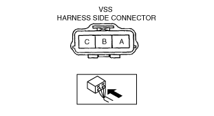
Power Supply Voltage Inspection
1. Disconnect the VSS connector.
2. Turn the ignition switch to ON.
3. Measure voltage at VSS connector terminal A (wiring harness side).
-
Vehicle speed sensor (VSS) voltage
-
B+
-
• If voltage is normal, go to Open Circuit Inspection and Short Circuit Inspection.
• If there is any malfunction, repair wiring harness between VSS and PCM.
Open Circuit Inspection
1. Inspect the following circuit for open.
-
• Power circuit (VSS connector terminal A to main relay terminal D)
• Ground circuit (VSS connector terminal C to GND)
• If an open circuit or short circuit is found, repair the malfunctioning wiring harness.
• If there are no open or short circuits, perform the sensor rotor inspection.
Short Circuit Inspection
1. Inspect the following circuit for short.
-
• Power circuit (VSS connector terminal A to main relay terminal D)
• If an open circuit or short circuit is found, repair the malfunctioning wiring harness.
• If there are no open or short circuits, perform the sensor rotor inspection.
Sensor Rotor Inspection
1. Remove the VSS. (See VEHICLE SPEED SENSOR (VSS) REMOVAL/INSTALLATION [FN4A-EL].)
2. Shift the selector lever to N position.
3. Inspect sensor rotor surface via VSS installation hole while rotating the front tire manually.
- (1) Is sensor rotor free of damage and cracks?
- (2) Is sensor rotor free of any metallic shavings or particles?
-
-
• If sensor rotor is normal, replace the VSS.
• If there is any malfunction, clean or replace the sensor rotor.