1. Inspect the speedometer by setting it to the input/output check mode check code 12. (See INSTRUMENT CLUSTER INPUT/OUTPUT CHECK MODE.)
1. Adjust the tire air pressure to the specification.
2. Using a speedometer tester, verify that the speedometer indication is within the allowable ranges shown below.
|
Speedometer tester indication (km/h)
|
Allowable range (km/h)
|
|---|---|
|
20
|
18-22
|
|
40
|
38-41
|
|
60
|
58-61
|
|
80
|
77-81
|
|
100
|
96-100
|
|
120
|
115-120
|
|
140
|
134-140
|
3. Verify that fluctuation of the speedometer needle is within the allowable range.
1. Inspect the tachometer by setting it to the input/output check mode check code 13. (See INSTRUMENT CLUSTER INPUT/OUTPUT CHECK MODE.)
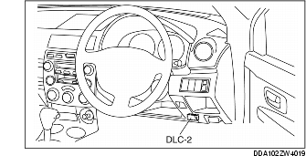
1. Connect the WDS or equivalent to the vehicle DLC-2 16-pin connector.
2. Access and monitor PIDs using the WDS or equivalent.
1. Inspect the fuel gauge by setting it to the input/output check mode check code 23. (See INSTRUMENT CLUSTER INPUT/OUTPUT CHECK MODE.)
1. Inspect the water temperature gauge by setting it to the input/output check mode check code 25. (See INSTRUMENT CLUSTER INPUT/OUTPUT CHECK MODE.)