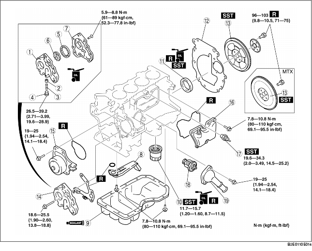
1. Assemble in the order indicated in the table.
|
1
|
Oil pump body
|
|
2
|
Control plunger
|
|
3
|
Plunger spring
|
|
4
|
Plunger plug
|
|
5
|
Outer rotor
|
|
6
|
Inner rotor
|
|
7
|
Oil pump cover
|
|
8
|
Oil strainer
|
|
9
|
Oil pan
(See Oil Pan Assembly Note)
|
|
10
|
Oil filter
(See Oil Filter Assembly Note)
|
|
11
|
Rear oil seal
|
|
12
|
End plate
|
|
13
|
Drive plate (ATX), flywheel (MTX)
|
|
14
|
Oil pump
(See Oil Pump Assembly Note)
|
|
15
|
Water pump
|
|
16
|
Oil separator
|
|
17
|
Knock sensor
|
|
18
|
Thermostat
|
|
19
|
Thermostat cover
|
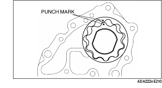
1. Assemble the inner rotor and the outer rotor with the punch marks aligned.
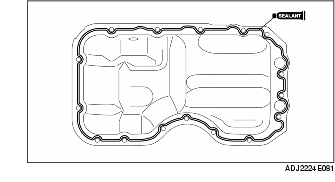
1. Apply silicone sealant as shown in the figure.
Diameter
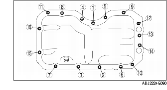
2. Tighten the oil pan installation bolts in the order shown in the figure.
Tightening torque
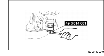
1. Install the oil filter using the SST.
Tightening torque
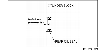
1. Apply clean engine oil to a new rear oil seal.
2. Insert the rear oil seal to the cylinder block by hand.
3. Install the rear oil seal using the SST.
1. Lock the drive plate (ATX) or flywheel (MTX) against rotation using the SST.
2. Tighten the flywheel installation bolts in two to three passes in the order shown in the figure.
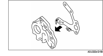
1. Install the gasket to the oil pump.
2. Install the oil pump and gasket as a single unit.
1. Install the knock sensor using the SST.