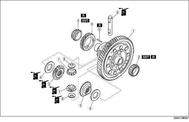
1. Assemble in the order indicated in the table.
|
1
|
Ring gear and gear case component
|
|
2
|
Bearing (ring gear side)
|
|
3
|
Speedometer drive gear
|
|
4
|
Bearing (side opposite ring gear)
|
|
5
|
Side gear
|
|
6
|
Thrust washer
|
|
7
|
Pinion gear
|
|
8
|
Thrust washer
|
|
9
|
Pinion shaft
|
|
10
|
Roll pin
(See Roll Pin Assembly Note.)
|
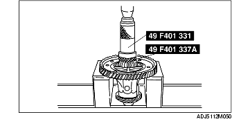
1. Install the new bearing using the SSTs.
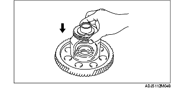
1. Install the speedometer drive gear as shown in the figure.
1. Install the speedometer drive gear.
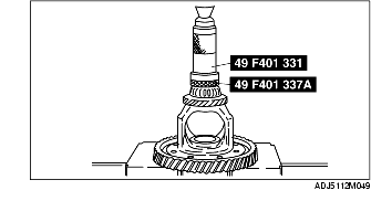
2. Install the new bearing using the SSTs.
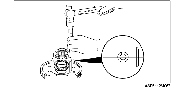
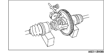
1. Install the new roll pin as shown in the figure to hold the pinion shaft.
2. Measure the backlash by the following procedure.
Thrust washer thickness