 |
am2zzw00004006
ON-BOARD DIAGNOSTIC TEST [MZ-CD 1.6 (Y6)]
id0102c3801000
DTC Reading Procedure
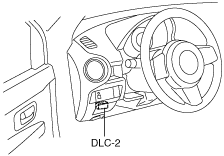
1. Connect the M-MDS to the DLC‐2.
am2zzw00004006
|
2. After the vehicle is identified, select the following items from the initialization screen of the M-MDS.
3. Then, select the “Retrieve CMDTCs” and perform procedures according to directions on the M-MDS screen.
4. Verify the DTC according to the directions on the M-MDS screen.
5. After completion of repairs, clear all DTCs stored in the PCM, while referring to “AFTER REPAIR PROCEDURE“. (See AFTER REPAIR PROCEDURE [MZ-CD 1.6 (Y6)].)
Pending Trouble Code Access Procedure
1. Connect the M-MDS to the DLC‐2.
am2zzw00004006
|
2. After the vehicle is identified, select the following items from the initialization screen of the M-MDS.
3. Then, select the “Retrieve CMDTCs” and perform procedures according to directions on the M-MDS screen.
4. Retrieve the pending trouble codes according to the directions on the M-MDS screen.
Freeze Frame PID Data Access Procedure
1. Connect the M-MDS to the DLC‐2.
am2zzw00004006
|
2. After the vehicle is identified, select the following items from the initialization screen of the M-MDS.
3. Then, select the “Retrieve CMDTCs” and perform procedures according to directions on the M-MDS screen.
4. Retrieve the freeze frame PID data according to the directions on the M-MDS screen.
Freeze frame data table
|
Freeze frame data item |
Unit |
Description |
Corresponding PID data monitor item |
|---|---|---|---|
|
LOAD
|
%
|
Calculated engine load
|
LOAD
|
|
ECT
|
°C
|
Engine coolant temperature
|
ECT
|
|
MAP
|
kPa
|
Manifold absolute pressure
|
MAP
|
|
RPM
|
RPM
|
Engine speed
|
RPM
|
|
VS
|
KPH
|
Vehicle speed
|
VSS
|
|
IAT
|
°C
|
Intake air temperature
|
IAT
|
|
MAF
|
g/sec
|
Mass airflow
|
MAF
|
|
EGRPCT
|
%
|
Target EGR valve position
|
SEGRP_DSD
|
|
FRP
|
kPa
|
Fuel pressure
|
FRP
|
|
BARO
|
kPa
|
Barometric pressure
|
BARO
|
|
APP_D
|
%
|
Accelerator pedal position No.1
|
APP1
|
Snapshot data table
|
Snapshot data item |
Unit |
Definition |
Corresponding PID data monitor item |
|---|---|---|---|
|
LOAD
|
%
|
Calculated engine load
|
LOAD
|
|
ECT
|
°C
|
Engine coolant temperature
|
ECT
|
|
MAP
|
Pa
|
Manifold absolute pressure
|
MAP
|
|
RPM
|
RPM
|
Engine speed
|
RPM
|
|
VSS
|
KPH
|
Vehicle speed
|
VSS
|
|
BAT
|
°C
|
Intake air temperature after super charged
|
BAT
|
|
MAF
|
g/sec
|
Mass airflow
|
MAF
|
|
ISV_POS
|
%
|
Intake shutter valve position
|
—
|
|
FRP
|
Pa
|
Fuel pressure
|
FRP
|
|
O2S11
|
V
|
Oxygen sensor output voltage
|
—
|
|
A
|
Oxygen sensor output current
|
—
|
|
|
CLR_CNT
|
—
|
Number of warm-up cycles after DTC cleared
|
—
|
|
CLR_DIST
|
km
|
Mileage after DTC cleared
|
—
|
|
BARO
|
Pa
|
Barometric pressure
|
BARO
|
|
EQ_RAT11
|
—
|
Equivalence ratio (Lambda)
|
—
|
|
EXHTEMP1
|
°C
|
Exhaust gas temperature (upper)
|
CATT11_DSD
|
|
EXHTEMP2
|
°C
|
Exhaust gas temperature (middle)
|
—
|
|
EXHTEMP3
|
°C
|
Exhaust gas temperature (lower)
|
CATT12_DSD
|
|
VPWR
|
V
|
Module supply voltage
|
VPWR
|
|
IAT
|
°C
|
Intake air temperature
|
IAT
|
|
APP1
|
%
|
Accelerator pedal position No.1
|
APP1
|
|
APP2
|
%
|
Accelerator pedal position No.2
|
APP2
|
|
ISV_DSD
|
%
|
Target intake shutter valve opening angle
|
ETC_DSD
|
On-Board System Readiness Tests Access Procedure
1. Connect the M-MDS to the DLC‐2.
am2zzw00004006
|
2. After the vehicle is identified, select the following items from the initialization screen of the M-MDS.
3. Then, select the “***SUP” and “**EVAL” PIDs in the PID selection screen.
4. Monitor those PIDs and check it system monitor is completed.
PID/DATA Monitor And Record Procedure
1. Connect the M-MDS to the DLC‐2.
am2zzw00004006
|
2. After the vehicle is identified, select the following items from the initialization screen of the M-MDS.
3. Select the PID from the PID table.
4. Verify the PID data according to the directions on the M-MDS screen.