 |
am2zzw00003582
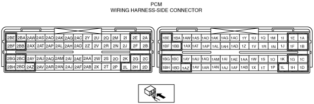
PCM INSPECTION [ZJ, ZY]
id0140c4802500
Without Using the M-MDS
PCM terminal voltage table (Reference)
am2zzw00003582
|
|
Terminal |
Signal name |
Connected to |
Test condition |
Voltage (V) |
Inspection item |
|
|---|---|---|---|---|---|---|
|
1A*8
|
Ground
|
Input/turbine speed sensor shield wire
|
Under any condition
|
Below 1.0
|
• Related wiring harness
|
|
|
1B
|
APP sensor No.1 ground
|
APP sensor
|
Under any condition
|
Below 1.0
|
• Related wiring harness
|
|
|
1C
|
APP sensor No.2 ground
|
APP sensor
|
Under any condition
|
Below 1.0
|
• Related wiring harness
|
|
|
1D*8
|
Shift solenoid A
|
Shift solenoid A
|
• Shift solenoid A
• Related wiring harness
|
|||
|
1E
|
APP sensor No.1 power supply
|
APP sensor
|
Under any condition
|
Approx. 5.0
|
• Related wiring harness
|
|
|
1F
|
APP sensor No.2 power supply
|
APP sensor
|
Under any condition
|
Approx. 5.0
|
• Related wiring harness
|
|
|
1G
|
Brake switch
|
Brake switch
|
Brake pedal depressed
|
B+
|
• Brake switch
• Related wiring harness
|
|
|
Brake pedal released
|
Below 1.0
|
|||||
|
1H*8
|
Shift solenoid B
|
Shift solenoid B
|
• Shift solenoid B
• Related wiring harness
|
|||
|
1I*1
|
Brake switch No.2
|
Brake switch No.2
|
Brake pedal depressed
|
B+
|
• Brake switch No.2
• Related wiring harness
|
|
|
Brake pedal released
|
Below 1.0
|
|||||
|
1J*2
|
Neutral switch
|
Neutral switch
|
Ignition switch is turned to the ON position.
|
Neutral
|
Below 1.0
|
• Neutral switch
• Related wiring harness
|
|
Except above
|
B+
|
|||||
|
1K*8
|
Shift solenoid D
|
Shift solenoid D
|
Idle
|
P position
|
B+
|
• Shift solenoid D
• Related wiring harness
|
|
R position
|
Below 1.0
|
|||||
|
N position
|
B+
|
|||||
|
D range
|
Below 1.0
|
|||||
|
S range
|
Below 1.0
|
|||||
|
L range
|
Below 1.0
|
|||||
|
1L*8
|
Shift solenoid C
|
Shift solenoid C
|
• Shift solenoid C
• Related wiring harness
|
|||
|
1M*2
|
CPP switch
|
CPP switch
|
Ignition switch is turned to the ON position.
|
Clutch pedal is depressed
|
Below 1.0
|
• CPP switch
• Related wiring harness
|
|
Clutch pedal is released
|
B+
|
|||||
|
1N*8
|
Hold switch
|
Hold switch
|
Ignition switch is turned to the ON position.
|
Hold switch depressed
|
Below 1.0
|
• Hold switch
• Related wiring harness
|
|
Hold switch released
|
B+
|
|||||
|
1O*8
|
Shift solenoid E
|
Shift solenoid E
|
Idle
|
P position
|
Below 1.0
|
• Shift solenoid E
• Related wiring harness
|
|
R position
|
Below 1.0
|
|||||
|
N position
|
Below 1.0
|
|||||
|
D range
|
Below 1.0
|
|||||
|
S range
|
Below 1.0
|
|||||
|
L range (normal)
|
Below 1.0
|
|||||
|
L range (HOLD)
|
B+
|
|||||
|
1P*8
|
Pressure control solenoid (+)
|
Pressure control solenoid
|
Idle
|
B+
|
• Pressure control solenoid
• Related wiring harness
|
|
|
1Q
|
—
|
—
|
—
|
—
|
—
|
|
|
1R*8
|
Input/turbine speed sensor (+)
|
Input/turbine speed sensor
|
• Input/turbine speed sensor
• Related wiring harness
|
|||
|
1S
|
—
|
—
|
—
|
—
|
—
|
|
|
1T*8
|
Pressure control solenoid (–)
|
Pressure control solenoid
|
• Pressure control solenoid
• Related wiring harness
|
|||
|
1U
|
—
|
—
|
—
|
—
|
—
|
|
|
1V*8
|
Input/turbine speed sensor (–)
|
Input/turbine speed sensor
|
• Input/turbine speed sensor
• Related wiring harness
|
|||
|
1W
|
—
|
—
|
—
|
—
|
—
|
|
|
1X*3
|
Starter relay
|
Starter relay
|
Cranking
|
Below 1.0
|
• Starter relay
• Related wiring harness
|
|
|
1Y
|
—
|
—
|
—
|
—
|
—
|
|
|
1Z
|
APP sensor No.1
|
APP sensor
|
Ignition switch is turned to the ON position.
|
Accelerator pedal depressed
|
Approx. 3.9
|
• APP sensor
• Related wiring harness
|
|
Accelerator pedal released
|
Approx. 1.6
|
|||||
|
1AA
|
—
|
—
|
—
|
—
|
—
|
|
|
1AB
|
—
|
—
|
—
|
—
|
—
|
|
|
1AC
|
Refrigerant pressure switch (middle)
|
Refrigerant pressure switch (middle)
|
Refrigerant pressure is more than the specification. (Refrigerant pressure switch (middle) is on.)
|
Below 1.0
|
• Refrigerant pressure switch (middle)
• Related wiring harness
|
|
|
Refrigerant pressure is less than the specification. (Refrigerant pressure switch (middle) is off.)
|
Approx. 5.0
|
|||||
|
1AD
|
APP sensor No.2
|
APP sensor
|
Ignition switch is turned to the ON position.
|
Accelerator pedal depressed
|
Approx. 3.4
|
• APP sensor
• Related wiring harness
|
|
Accelerator pedal released
|
Approx. 1.0
|
|||||
|
1AE
|
CAN_H
|
CAN system related module, DLC-2
|
Because this terminal is for CAN, no valid determination of terminal voltage is possible.
|
• Related wiring harness
|
||
|
1AF*1
|
Cruise control switch
|
Cruise control switch
|
Under any condition
|
Below 1.0
|
• Cruise control switch
|
|
|
1AG*4
|
Ground
|
Evaporator temperature sensor, TFT sensor, TR switch
|
Under any condition
|
Below 1.0
|
• Related wiring harness
|
|
|
1AH*8
|
ATF temperature
|
ATF sensor
|
Ignition switch is turned to the ON position.
|
ATF temperature is 20 °C {68 °F}
|
Approx. 3.3
|
• ATF sensor
• Related wiring harness
|
|
ATF temperature is 40 °C {104 °F}
|
Approx. 2.4
|
|||||
|
ATF temperature is 60 °C {140 °F}
|
Approx. 1.5
|
|||||
|
1AI
|
CAN_L
|
CAN system related module, DLC-2
|
Because this terminal is for CAN, no valid determination of terminal voltage is possible.
|
• Related wiring harness
|
||
|
1AJ
|
Main relay
|
Main relay
|
Ignition switch off and a certain period has elapsed.
|
B+
|
• Main relay
• Related wiring harness
|
|
|
Ignition switch is turned to the ON position.
|
Below 1.5
|
|||||
|
1AK
|
—
|
—
|
—
|
—
|
—
|
|
|
1AL
|
—
|
—
|
—
|
—
|
—
|
|
|
1AM
|
—
|
—
|
—
|
—
|
—
|
|
|
1AN
|
A/C cut-off control
|
A/C relay
|
Idle, A/C operating
|
Below 1.0
|
• A/C relay
• Related wiring harness
|
|
|
Idle, A/C not operating
|
B+
|
|||||
|
1AO
|
A/C
|
Refrigerant pressure switch (high, low), A/C amplifier
|
Refrigerant pressure is more than the specification or less than the specification. (Refrigerant pressure switch (high, low) is off.)
|
Approx. 5.0
|
• Refrigerant pressure switch (high, low)
• A/C amplifier
• Related wiring harness
|
|
|
Except above
|
Below 2.0*4
Approx. 3.0*5
|
|||||
|
1AP
|
—
|
—
|
—
|
—
|
—
|
|
|
1AQ*3
|
Fuel pump control
|
Fuel pump relay
|
Ignition switch is turned to the ON position and a certain period has elapsed.
|
B+
|
• Fuel pump relay
• Related wiring harness
|
|
|
Cranking
|
Below 1.0
|
|||||
|
Idle
|
||||||
|
1AR*6
|
Fuel pump control
|
Fuel pump relay
|
Ignition switch is turned to the ON position and a certain period has elapsed.
|
B+
|
• Fuel pump relay
• Related wiring harness
|
|
|
Cranking
|
Below 1.0
|
|||||
|
Idle
|
||||||
|
1AS*8
|
Selector lever position
|
TR switch
|
Ignition switch is turned to the ON position.
|
P position
|
Approx. 4.6
|
• TR switch
• Related wiring harness
|
|
R position
|
Approx. 3.9
|
|||||
|
N position
|
Approx. 3.3
|
|||||
|
D range
|
Approx. 2.5
|
|||||
|
S range
|
Approx. 1.7
|
|||||
|
L range
|
Approx. 0.9
|
|||||
|
1AT
|
—
|
—
|
—
|
—
|
—
|
|
|
1AU*1
|
Cruise control switch
|
Cruise control switch
|
Ignition switch to the ON position
|
ON switch pressed in
|
Approx. 4.05
|
• Cruise control switch
|
|
OFF switch pressed in
|
Approx. 0.05
|
|||||
|
CANCEL switch pressed in
|
Approx. 0.98
|
|||||
|
SET(+) switch pressed in
|
Approx. 2.73
|
|||||
|
SET(-) switch pressed in
|
Approx. 1.88
|
|||||
|
RESUME switch pressed in
|
Approx. 3.45
|
|||||
|
1AV
|
Cooling fan control
|
Cooling fan relay No.1
|
During test mode*7
|
Accelerator pedal released
|
B+
|
• Cooling fan relay No.1
• Related wiring harness
|
|
Accelerator pedal depressed
|
Below 1.0
|
|||||
|
1AW*4
|
Evaporator temperature sensor
|
Evaporator temperature sensor
|
Ignition switch is turned to the ON position.
|
Evaporator temperature is 20 °C {68 °F}
|
Approx. 2.5
|
• Evaporator temperature sensor
• Related wiring harness
|
|
1AX*8
|
Vehicle speed
|
VSS
|
• VSS
• Related wiring harness
|
|||
|
1AY
|
—
|
—
|
—
|
—
|
—
|
|
|
1AZ
|
Cooling fan control
|
Cooling fan relay No.2
|
During test mode*7
|
Accelerator pedal released
|
B+
|
• Cooling fan relay No.2
• Related wiring harness
|
|
Accelerator pedal depressed
|
Below 1.0
|
|||||
|
1BA*5
|
ECT output
|
Climate control unit
|
Ignition switch is turned to the ON position.
|
ECT is 20 °C {68 °F}
|
Approx. 3.0
|
• Climate control unit
• Related wiring harness
|
|
ECT is 60 °C {140 °F}
|
Approx. 1.4
|
|||||
|
ECT is 80 °C {176 °F}
|
Approx. 0.9
|
|||||
|
1BB
|
B+
|
Main relay
|
Ignition switch off.
|
Below 1.0
|
• Main relay
• Battery
• Related wiring harness
|
|
|
Ignition switch is turned to the ON position.
|
B+
|
|||||
|
1BC
|
Back-up power supply
|
Battery
|
Under any condition
|
B+
|
• Battery
• Related wiring harness
|
|
|
1BD
|
—
|
—
|
—
|
—
|
—
|
|
|
1BE
|
Drive-by-wire control
|
Main relay
|
Ignition switch is turned to the ON position.
|
Drive-by-wire system is malfunction
|
Below 1.0
|
• Drive-by-wire relay
• Related wiring harness
|
|
Drive-by-wire system is normal
|
B+
|
|||||
|
1BF
|
B+
|
Main relay
|
Ignition switch off.
|
Below 1.0
|
• Main relay
• Battery
• Related wiring harness
|
|
|
Ignition switch is turned to the ON position.
|
B+
|
|||||
|
1BG*8
|
B+
|
Main relay
|
Ignition switch off.
|
Below 1.0
|
• Main relay
• Battery
• Related wiring harness
|
|
|
Ignition switch is turned to the ON position.
|
B+
|
|||||
|
1BH
|
Ignition switch
|
Ignition switch
|
Ignition switch off
|
Below 1.0
|
• Ignition switch
• Related wiring harness
|
|
|
Ignition switch is turned to the ON position.
|
B+
|
|||||
|
2A
|
Fuel injection control
|
Fuel injector No.1
|
• Fuel injector No.1
• Related wiring harness
|
|||
|
2B
|
Fuel injection control
|
Fuel injector No.2
|
• Fuel injector No.2
• Related wiring harness
|
|||
|
2C
|
Fuel injection control
|
Fuel injector No.3
|
• Fuel injector No.3
• Related wiring harness
|
|||
|
2D
|
Ignition coil power supply
|
Ignition coil
|
Ignition switch is turned to the ON position.
|
B+
|
• Related wiring harness
|
|
|
2E
|
Fuel injector No.1 power supply
|
Fuel injector No.1
|
Ignition switch is turned to the ON position.
|
B+
|
• Related wiring harness
|
|
|
2F
|
Fuel injector No.2 power supply
|
Fuel injector No.2
|
Ignition switch is turned to the ON position.
|
B+
|
• Related wiring harness
|
|
|
2G
|
Fuel injector No.3 power supply
|
Fuel injector No.3
|
Ignition switch is turned to the ON position.
|
B+
|
• Related wiring harness
|
|
|
2H
|
Fuel injection control
|
Fuel injector No.4
|
• Fuel injector No.4
• Related wiring harness
|
|||
|
2I
|
Power supply
|
CMP sensor, Purge solenoid valve, OCV, CKP sensor
|
Ignition switch is turned to the ON position.
|
B+
|
• Related wiring harness
|
|
|
2J
|
Ground
|
ECT sensor, HO2S, MAP sensor, KS shield wire
|
Under any condition
|
Below 1.0
|
• Related wiring harness
|
|
|
2K
|
EGR control
|
EGR valve
|
Idle (EGR control operating)
|
Below 1.0
|
• EGR valve
• Related wiring harness
|
|
|
2L
|
Fuel injector No.4 power supply
|
Fuel injector No.4
|
Ignition switch is turned to the ON position.
|
B+
|
• Related wiring harness
|
|
|
2M
|
Ground
|
CMP sensor, CKP sensor
|
Under any condition
|
Below 1.0
|
• Related wiring harness
|
|
|
2N
|
CMP
|
CMP sensor
|
• CMP sensor
• Related wiring harness
|
|||
|
2O
|
EGR control
|
EGR valve
|
Idle (EGR control operating)
|
B+
|
• EGR valve
• Related wiring harness
|
|
|
2P
|
EGR control
|
EGR valve
|
Idle (EGR control operating)
|
B+
|
• EGR valve
• Related wiring harness
|
|
|
2Q
|
Ground
|
IAT sensor
|
Under any condition
|
Below 1.0
|
• Related wiring harness
|
|
|
2R
|
IAT
|
IAT sensor
|
Ignition switch is turned to the ON position.
|
IAT is 20 °C {68 °F}
|
Approx. 2.2
|
• IAT sensor
• Related wiring harness
|
|
IAT is 30 °C {86 °F}
|
Approx. 1.8
|
|||||
|
2S
|
Evaporative purge control
|
Purge solenoid valve
|
• Purge solenoid valve
• Related wiring harness
|
|||
|
2T
|
EGR control
|
EGR valve
|
Idle (EGR control operating)
|
B+
|
• EGR valve
• Related wiring harness
|
|
|
2U
|
Ground
|
MAF sensor
|
Under any condition
|
Below 1.0
|
• Related wiring harness
|
|
|
2V
|
MAF
|
MAF sensor
|
Ignition switch is turned to the ON position.
|
Approx. 0.7
|
• MAF sensor
• Related wiring harness
|
|
|
Idle
|
Approx. 1.3
|
|||||
|
2W
|
Variable valve timing control
|
OCV
|
• OCV
• Related wiring harness
|
|||
|
2X
|
A/F sensor heater control
|
A/F sensor (heater)
|
• A/F sensor
• Related wiring harness
|
|||
|
2Y
|
CKP
|
CKP sensor
|
• CKP sensor
• Related wiring harness
|
|||
|
2Z
|
A/F sensor
|
A/F sensor
|
Idle (after warm-up)
|
Approx. 0
|
• A/F sensor
• Related wiring harness
|
|
|
2AA
|
—
|
—
|
—
|
—
|
—
|
|
|
2AB
|
HO2S heater control
|
HO2S (heater)
|
Idle (after warm-up)
|
Below 1.0
|
• HO2S
• Related wiring harness
|
|
|
Heavy load
|
B+
|
|||||
|
2AC
|
ECT
|
ECT sensor
|
Ignition switch is turned to the ON position.
|
ECT is 20 °C {68 °F}
|
Approx. 3.0
|
• ECT sensor
• Related wiring harness
|
|
ECT is 60 °C {140 °F}
|
Approx. 1.4
|
|||||
|
ECT is 80 °C {176 °F}
|
Approx. 0.9
|
|||||
|
2AD
|
A/F sensor
|
A/F sensor
|
Idle (after warm-up)
|
Approx. 2.4
|
• A/F sensor
• Related wiring harness
|
|
|
2AE
|
Generator output voltage
|
Generator (terminal P: stator coil)
|
• Generator
• Related wiring harness
|
|||
|
2AF
|
Generator field coil control
|
Generator (terminal D: field coil)
|
• Generator
• Related wiring harness
|
|||
|
2AG
|
Variable tumble control (open)
|
Variable tumble shutter valve actuator
|
The engine is hot.
|
Directly after the ignition switch is turned to the ON position.
|
B+*9
|
• Variable tumble shutter valve actuator
• Related wiring harness
|
|
Idle after cold start.
|
When the ECT is increased instant and reaches 60 °C {140 °F}
|
|||||
|
Except above
|
Below 1.0
|
|||||
|
2AH
|
HO2S
|
HO2S
|
Idle (after warm-up)
|
Alternates between 0 and 1.0
|
• HO2S
• Related wiring harness
|
|
|
2AI*10
|
Variable intake air control (close)
|
Variable intake air shutter valve actuator
|
Directly after the ignition switch is turned to the ON position.
|
B+*9
|
• Variable intake air shutter valve actuator
• Related wiring harness
|
|
|
When the engine speed is decreased gradually and reaches 4,100 rpm.
|
||||||
|
Except above
|
Below 1.0
|
|||||
|
2AJ*10
|
Variable intake air control (open)
|
Variable intake air shutter valve actuator
|
Directly after the ignition switch is turned to the ON position.
|
Below 1.0
|
• Variable intake air shutter valve actuator
• Related wiring harness
|
|
|
When the engine speed is increased gradually and reaches 4,100 rpm.
|
B+*9
|
|||||
|
Except above
|
Below 1.0
|
|||||
|
2AK
|
Variable tumble control (close)
|
Variable tumble shutter valve actuator
|
The engine is cold.
|
Directly after the ignition switch is turned to the ON position.
|
B+*9
|
• Variable tumble shutter valve actuator
• Related wiring harness
|
|
Except above
|
Below 1.0
|
|||||
|
2AL
|
—
|
—
|
—
|
—
|
—
|
|
|
2AM
|
—
|
—
|
—
|
—
|
—
|
|
|
2AN
|
Knocking
|
KS
|
Ignition switch is turned to the ON position. (Use digital type voltmeter, because measurement voltage will be detected less than true voltage when using analog type voltmeter.)
|
Approx. 2.4
|
• KS
• Related wiring harness
|
|
|
2AO
|
Power supply
|
MAP sensor
|
Ignition switch is turned to the ON position.
|
Approx. 5.0
|
• Related wiring harness
|
|
|
2AP
|
MAP sensor
|
MAP sensor
|
Ignition switch is turned to the ON position.
|
Barometric pressure: 13—200 kPa {98—1,500 mmHg, 3.8—59.1 inHg}
|
1.0—4.5
|
• MAP sensor
• Related wiring harness
|
|
2AQ
|
ESA control
|
Ignition coil No.1
|
• Ignition coil No.1
• Related wiring harness
|
|||
|
2AR
|
ESA control
|
Ignition coil No.2
|
• Ignition coil No.2
• Related wiring harness
|
|||
|
2AS
|
TP sensor power supply
|
Throttle body (TP sensor)
|
Under any condition
|
Approx. 5.0
|
• Related wiring harness
|
|
|
2AT
|
TP sensor No.2
|
Throttle body (TP sensor)
|
Ignition switch is turned to the ON position.
|
Accelerator pedal depressed
|
Approx. 0.5
|
• TP sensor
• Related wiring harness
|
|
Accelerator pedal released
|
Approx. 3.9
|
|||||
|
2AU
|
ESA control
|
Ignition coil No.3
|
• Ignition coil No.3
• Related wiring harness
|
|||
|
2AV
|
ESA control
|
Ignition coil No.4
|
• Ignition coil No.4
• Related wiring harness
|
|||
|
2AW
|
TP sensor ground
|
Throttle body (TP sensor)
|
Under any condition
|
Below 1.0
|
• Related wiring harness
|
|
|
2AX
|
TP sensor No.1
|
Throttle body (TP sensor)
|
Ignition switch is turned to the ON position.
|
Accelerator pedal depressed
|
Approx. 4.5
|
• TP sensor
• Related wiring harness
|
|
Accelerator pedal released
|
Approx. 1.1
|
|||||
|
2AY
|
—
|
—
|
—
|
—
|
—
|
|
|
2AZ
|
Ground
|
Body ground
|
Under any condition
|
Below 1.0
|
• Related wiring harness
|
|
|
2BA
|
Ground
|
Body ground
|
Under any condition
|
Below 1.0
|
• Related wiring harness
|
|
|
2BB
|
Ground
|
Body ground
|
Under any condition
|
Below 1.0
|
• Related wiring harness
|
|
|
2BC
|
Power supply
|
MAF sensor, EGR valve
|
Idle
|
B+
|
• Related wiring harness
|
|
|
2BD
|
Ground
|
Body ground
|
Under any condition
|
Below 1.0
|
• Related wiring harness
|
|
|
2BE
|
Throttle control (–)
|
Throttle body (throttle valve actuator)
|
• Throttle valve actuator
• Related wiring harness
|
|||
|
2BF
|
Throttle control (+)
|
Throttle body (throttle valve actuator)
|
• Throttle valve actuator
• Related wiring harness
|
|||
|
2BG
|
Ground
|
A/F sensor shield wire, HO2S shield wire
|
Under any condition
|
Below 1.0
|
• Related wiring harness
|
|
|
2BH
|
Ground
|
Body ground
|
Under any condition
|
Below 1.0
|
• Related wiring harness
|
|
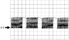
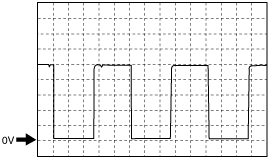
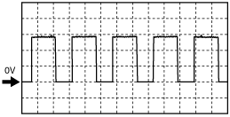
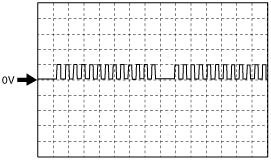
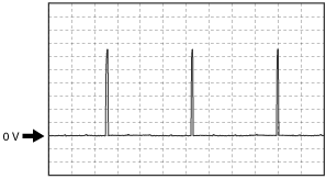
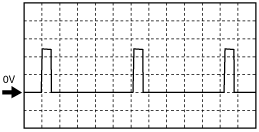
Inspection Using An Oscilloscope (Reference)
Shift solenoid A signal
am2zzw00003583
|
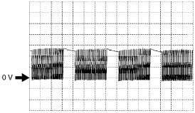
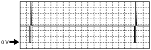
Shift solenoid B signal
am2zzw00003584
|
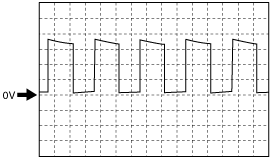
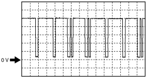
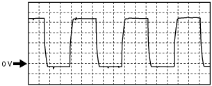
Shift solenoid C signal
am2zzw00003585
|
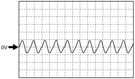
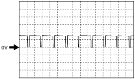
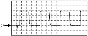
Input/turbine speed sensor signal
am2zzw00003586
|
Pressure control solenoid (–) signal
am2zzw00002249
|
Vehicle speed signal (ATX)
am2zzw00002250
|
Fuel injection control signal
am2zzw00001204
|
CMP signal
am2zzw00003587
|
Evaporative purge control signal
am2zzw00003588
|
Variable valve timing control signal
am2zzw00003589
|
A/F sensor heater control signal
am2zzw00003590
|
CKP signal
am2zzw00003591
|
Generator output voltage signal
am2zzw00001210
|
Generator field coil control signal
am2zzw00001211
|
ESA control signal
am2zzw00001212
|
Throttle control (–) signal
adejjw00002871
|
Throttle control (+) signal
am2zzw00003592
|
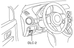
Using The M-MDS
1. Connect the M-MDS to the DLC-2.
am2zzw00001288
|
2. Turn the ignition switch to the ON position.
3. Measure the PID value.
|
Item (definition) |
Unit/Condition |
Condition/Specification (Reference) |
Inspection item(s) |
PCM terminal |
|||
|---|---|---|---|---|---|---|---|
|
A/CL V
(A/C load signal voltage)
|
V
|
Manual air conditioner
• A/C is not operating: Approx. 5.0 V
• A/C is operating: 2.0 V or less
|
• Refrigerant pressure switch (low, middle, high)
• A/C switch
• A/C amplifier
• Related wiring harness
|
1AO
|
|||
|
Full-auto air conditioner
• A/C is not operating: Approx. 5.0 V
• A/C is operating: Approx. 3.0 V
|
|||||||
|
A/CT
(Evaporator temperature)
|
°C
|
°F
|
Manual air conditioner
• Indicate the evaporator temperature.
|
• Evaporator temperature sensor
• Related wiring harness
|
1AW
|
||
|
Full-auto air conditioner
• -40 °C {-72 °F}
|
—
|
||||||
|
A/CT V
(Evaporator temperature signal voltage)
|
V
|
Manual air conditioner
• Evaporator temperature sensor is 20 °C {68 °F}: Approx. 2.5 V
|
• Evaporator temperature sensor
• Related wiring harness
|
1AW
|
|||
|
Full-auto air conditioner
• 4.98 V
|
—
|
||||||
|
AC_REQ
(Refrigerant pressure switch (high, low)
|
On/Off
|
• Refrigerant pressure is more than the specification or less than the specification. (Refrigerant pressure switch (high, low) is off.): Off
• Except above: On
|
• Refrigerant pressure switch (high, low)
• A/C amplifier
• Related wiring harness
|
1AO, 1AN
|
|||
|
ACCS
(A/C relay)
|
On/Off
|
• A/C relay is ON: On
• A/C relay is OFF: Off
|
• The following PIDs
|
1AO, 1AN
|
|||
|
AFR
(Target air/fuel ratio)
|
—
|
• Target air-fuel ratio is displayed
|
• A/F sensor
• Related wiring harness
|
—
|
|||
|
AFR_ACT
(Actual air/fuel ratio)
|
—
|
• Actual air-fuel ratio is displayed
|
• A/F sensor
• Related wiring harness
|
—
|
|||
|
ALTF
(Generator field coil control duty value)
|
%
|
• Ignition switch is turned to the ON position: 0 %
• Idle, E/L is operating: Duty value increases.
|
• Generator
• Related wiring harness
|
2AF
|
|||
|
ALTT V
(Generator output voltage)
|
V
|
• Idle (no E/L): Approx. 14 V (This is an internal calculation value and differs from the terminal voltage.)
|
• Generator
• Related wiring harness
|
2AE
|
|||
|
APP*3
(Accelerator pedal position)
|
%
|
• Accelerator pedal released: 0 %
• Accelerator pedal depressed: 100 %
|
• The following PIDs
|
—
|
|||
|
APP1
(APP sensor No.1)
|
%
|
• Accelerator pedal released: Approx. 32 %
• Accelerator pedal depressed: Approx. 78 %
|
• APP sensor
• Related wiring harness
|
1B, 1E, 1Z
|
|||
|
V
|
• Accelerator pedal released: Approx. 1.6 V
• Accelerator pedal depressed: Approx. 3.9 V
|
1Z
|
|||||
|
APP2
(APP sensor No.2)
|
%
|
• Accelerator pedal released: Approx. 21 %
• Accelerator pedal depressed: Approx. 67 %
|
• APP sensor
• Related wiring harness
|
1C, 1F, 1AD
|
|||
|
V
|
• Accelerator pedal released: Approx. 1.0 V
• Accelerator pedal depressed: Approx. 3.4 V
|
1AD
|
|||||
|
ARPMDES
(Target engine speed)
|
RPM
|
• Indicate the target engine speed.
|
• The following PIDs
|
—
|
|||
|
BOO
(Brake switch)
|
On/Off
|
• Brake pedal depressed: On
• Brake pedal released: Off
|
• Brake switch No.1
• Related wiring harness
|
1G
|
|||
|
BPA*2
(Brake pressure applied switch)
|
On/Off
|
• Brake pedal depressed: On
• Brake pedal released: Off
|
• Brake switch No.2
• Related wiring harness
|
1I
|
|||
|
CHRGLP
(Generator warning light)
|
On/Off
|
• Idle, Generator warning light illuminate: On
• Idle, Generator warning light not illuminate: Off
|
• Generator warning light
• Related wiring harness
|
—
|
|||
|
COLP
(Refrigerant pressure switch (middle))
|
On/Off
|
• Refrigerant pressure is more than the specification. (Refrigerant pressure switch (middle) is on.): On
• Refrigerant pressure is less than the specification. (Refrigerant pressure switch (middle) is off.): Off
|
• Refrigerant pressure switch (middle)
• Related wiring harness
|
1AC
|
|||
|
CPP*4
(Clutch pedal position)
|
On/Off
|
• Clutch pedal depressed: On
• Clutch pedal released: Off
|
• CPP switch
• Related wiring harness
|
1M
|
|||
|
CPP/PNP*4
(Shift lever position)
|
On/Off
|
• Neutral: On
• Other than neutral: Off
|
• Neutral switch
• Related wiring harness
|
1J
|
|||
|
ECT
(Engine coolant temperature)
|
°C
|
°F
|
• Ignition switch is turned to the ON position: Indicate the ECT
|
• ECT sensor
• Related wiring harness
|
—
|
||
|
V
|
• ECT is 20 °C {68 °F}: Approx. 3.0 V
• ECT is 60 °C {140 °F}: Approx. 1.4 V
• ECT is 80 °C {176 °F}: Approx. 0.9 V
|
2AC
|
|||||
|
EQ_RAT11
(Actual lambda signal)
|
—
|
• Idle after warm-up: Approx. 1
|
• A/F sensor
• Related wiring harness
|
—
|
|||
|
EQ_RAT11_DSD
(Target lambda)
|
—
|
• Target lambda (Excess air factor = supplied air amount / theoretical air/fuel ratio)
|
• A/F sensor
• Related wiring harness
|
—
|
|||
|
ETC_ACT
(Throttle control)
|
°
|
• Accelerator pedal released: 0 °
• Accelerator pedal depressed: 71.6 °
|
• TP sensor
• Related wiring harness
|
—
|
|||
|
ETC_DSD
(Throttle control desired)
|
%
|
• Indicate the target throttle valve opening ratio
|
• The following PIDs
|
—
|
|||
|
°
|
• Indicate the target throttle valve opening angle
|
||||||
|
EVAPCP
(Purge solenoid valve duty value)
|
%
|
• Ignition switch is turned to the ON position: 0 %
• Increase the engine speed (after warm-up): Duty value rises
|
• The following PIDs
• Purge solenoid valve
• Related wiring harness
|
—
|
|||
|
FAN1
(Cooling fan relay No.1 control signal)
|
On/Off
|
• During test mode
CTP: Off
WOT: On
|
• The following PIDs
|
1AV
|
|||
|
FAN2
(Cooling fan relay No.2 control signal)
|
On/Off
|
• During test mode
CTP: Off
WOT: On
|
• The following PIDs
|
1AZ
|
|||
|
FP
(Fuel pump relay)
|
On/Off
|
• Ignition switch is turned to the ON position and a certain period has elapsed: Off
• Cranking: On
• Idle: On
|
• Fuel pump relay
• Related wiring harness
|
1AQ*5, 1AR*6
|
|||
|
FUELPW
(Fuel injector duration)
|
sec
|
• Idle: Approx. 1.36 ms
|
• The following PIDs
|
—
|
|||
|
FUELSYS
(Fuel system status)
|
OL/CL/
OL_Drive/
OL_Fault/
CL_Fault
|
• Idle after warm-up: CL
|
• The following PIDs
|
—
|
|||
|
HTR12
(HO2S heater control)
|
On/Off
|
• Ignition switch is turned to the ON position: Off
• Idle: On
|
• The following PIDs
|
2AB, 2I
|
|||
|
IAT
(Intake air temperature)
|
°C
|
°F
|
• Ignition switch is turned to the ON position: Indicate the IAT
|
• IAT sensor
• Related wiring harness
|
—
|
||
|
V
|
• IAT is 20 °C {68 °F}: Approx. 2.2 V
• IAT is 30 °C {86 °F}: Approx. 1.8 V
|
2R
|
|||||
|
IMRC
(Variable tumble control)
|
On/Off
|
Measure when starting a cold engine.
• While the engine speed is increasing: On at 3,250 rpm
• While the engine speed is decreasing: Off at 3,160 rpm
|
• The following PIDs
|
—
|
|||
|
%
|
• Indicate the variable tumble shutter valve opening ratio
|
2AG, 2AK
|
|||||
|
IMTV*1
(Variable intake air control)
|
On/Off
|
• Engine speed is less than 4,100 rpm: On
• Engine speed is 4,100 rpm or more: Off
|
• The following PIDs
|
—
|
|||
|
%
|
• Indicate the variable intake air shutter valve opening ratio
|
2AI, 2AJ
|
|||||
|
INGEAR
(Gears are engaged)
|
On/Off
|
MTX
• When the following conditions are satisfied: On
• Except above: Off
|
• CPP switch
• Neutral switch
• Related wiring harness
|
1M
|
|||
|
ATX
• Driving range: On
• Except above: Off
|
• TR switch
• Related wiring harness
|
—
|
|||||
|
IVS
(CTP condition)
|
Idle/Off_Idle
|
• Idle: Idle
• Other than idle: Off Idle
|
• The following PIDs
|
—
|
|||
|
KNOCKR
(Knocking retard)
|
°
|
• Ignition switch is turned to the ON position: 0 °
• Idle: 0 °
|
• KS
• Related wiring harness
|
—
|
|||
|
LOAD
(Engine load)
|
%
|
• Idle after warm-up: Approx. 20 %
|
• The following PIDs
|
—
|
|||
|
LONGFT1
(Long term fuel trim)
|
%
|
• Idle after warm-up: Approx.-15—15 %
|
• The following PIDs
|
—
|
|||
|
MAF
(Mass air flow)
|
g/s
|
• Ignition switch is turned to the ON position: Approx. 0 g/s
• Idle: Approx. 2.7 g/s
|
• MAF sensor
• Related wiring harness
|
—
|
|||
|
V
|
• Ignition switch is turned to the ON position: Approx. 0.7 V
• Idle: Approx. 1.3 V
|
||||||
|
MAP
(Manifold absolute pressure)
|
kPa
|
psi
|
Bar
|
• Ignition switch is turned to the ON position: Indicate the MAP
|
• MAP sensor
• Related wiring harness
|
2J, 2AO, 2AP
|
|
|
V
|
• Ignition switch is turned to the ON position
|
2AP
|
|||||
|
MIL
(Malfunction indicator lamp)
|
On/Off
|
• Idle, MIL illuminate: On
• Idle, MIL not illuminate: Off
|
• MIL
• Related wiring harness
|
—
|
|||
|
MIL_DIS
(Travelled distance since MIL illuminated)
|
km
|
mile
|
Travelled distance since MIL illuminated
|
||||
|
O2S11
(A/F sensor)
|
A
|
• Idle after warm-up: Approx. 0 mA
|
• A/F sensor
• Related wiring harness
|
2Z, 2AD
|
|||
|
O2S12
(HO2S)
|
V
|
• Idle after warm-up: Alternates between 1.0 or less and B+
|
• HO2S
• Related wiring harness
|
2AH, 2J
|
|||
|
PCM_T
(PCM temperature sensor)
|
°C
|
• Indicate the PCM temperature.
|
• PCM
• Related wiring harness
|
—
|
|||
|
PCM_T_Max
(Maximum PCM temperature)
|
°C
|
• Ignition switch is turned to the ON position: Indicate the maximum PCM temperature.
|
• PCM
• Related wiring harness
|
—
|
|||
|
RO2FT1
(HO2S fuel trim)
|
%
|
• Idle after warm-up: Approx. 0
|
• The following PIDs
|
—
|
|||
|
RPM
(Engine speed)
|
RPM
|
• When the engine is running: Indicate the engine speed
|
• CKP sensor
• Related wiring harness
|
—
|
|||
|
SCCS*2
(Speed control command switch)
|
V
|
• Press ON: Approx. 4.05 V
• Press OFF: Approx. 0.05 V
• Press CANCEL: Approx. 0.98 V
• Press SET(+): Approx. 2.73 V
• Press SET(-): Approx. 1.88 V
• Press RESUME: Approx. 3.45 V
|
• Cruise control switsh
• Related wiring harness
|
1AF, 1AU
|
|||
|
SEGRP
(EGR control)
|
—
|
• Ignition switch is turned to the ON position: 0 Step
• Idle: 0 Step
• Engine speed is 1,200—4,200 rpm: 0—52 Step
|
• EGR valve
• Related wiring harness
|
—
|
|||
|
SEGRP DSD
(EGR valve position desired)
|
%
|
• Ignition switch is turned to the ON position: 0 %
• Idle: 0 %
• Engine speed is 1,200—4,200 rpm: 0—100 %
|
• The following PIDs
|
—
|
|||
|
SHRTFT1
(Short term fuel trim (front))
|
%
|
• Idle after warm-up:-25—25 %
|
• The following PIDs
|
—
|
|||
|
SPARKADV
(Ignition timing)
|
°
|
• Indicate the ignition timing
|
• The following PIDs
|
—
|
|||
|
TEST
(Test mode)
|
On/Off
|
• Test mode On: On
• Test mode Off: Off
|
—
|
—
|
|||
|
TP REL
(Throttle position signal (relative value))
|
%
|
• Accelerator pedal released: Approx. 13 %
• Accelerator pedal depressed: Approx. 81 %
|
• The following PIDs
|
—
|
|||
|
TP1
(TP sensor No.1)
|
V
|
• Accelerator pedal released: Approx. 1.1 V
• Accelerator pedal depressed: Approx. 4.5 V
|
• TP sensor
• Related wiring harness
|
2AX
|
|||
|
%
|
• Accelerator pedal released: Approx. 23%
• Accelerator pedal depressed: Approx. 91 %
|
2AX, 2AS, 2AW
|
|||||
|
TP2
(TP sensor No.2)
|
V
|
• Accelerator pedal released: Approx. 3.9 V
• Accelerator pedal depressed: Approx. 0.5 V
|
• TP sensor
• Related wiring harness
|
2AT
|
|||
|
%
|
• Accelerator pedal released: Approx. 22 %
• Accelerator pedal depressed: Approx. 91 %
|
2AT, 2AS, 2AW
|
|||||
|
TPCT
(TP sensor voltage at CTP)
|
V
|
• Ignition switch is turned to the ON position: Approx. 1 V
|
• The following PIDs
|
—
|
|||
|
VPWR
(Battery positive voltage)
|
V
|
• Indicate the battery voltage
|
• Battery
• Main relay
• Related wiring harness
|
—
|
|||
|
VSS
(Vehicle speed)
|
Km/h
|
mph
|
• Vehicle running: Indicate the vehicle speed
|
• VSS
• ABS HU/CM
• Related wiring harness
|
—
|
||
|
VT ACT1
(Actual valve timing)
|
°
|
• Idle: Approx. 0 °
• Racing (after warm-up): 0—35 °
|
• The following PIDs
• CMP sensor
• Related wiring harness
|
2N
|
|||
|
VT DIFF1
(Difference between target valve timing and actual valve timing)
|
°
|
• Idle: 0 °
|
• The following PIDs
• OCV
• Related wiring harness
|
2W
|
|||
|
VT DUTY1
(OCV control)
|
%
|
• Idle: Approx. 10 %
|
• The following PIDs
|
—
|
|||