 |
am2zzw00003538
JOINT SHAFT REMOVAL/INSTALLATION [ZJ, ZY]
id0313008009a8
1. Drain the transaxle oil or ATF. (See TRANSAXLE OIL REPLACEMENT [F35M-R].) (See AUTOMATIC TRANSAXLE FLUID (ATF) REPLACEMENT.)
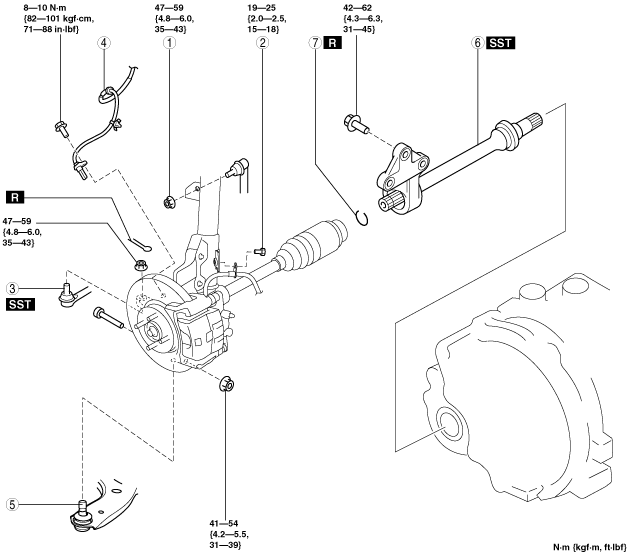
2. Remove in the order indicated in the table.
3. Install in the reverse order of removal.
4. Add the transaxle oil or ATF. (See TRANSAXLE OIL REPLACEMENT [F35M-R].) (See AUTOMATIC TRANSAXLE FLUID (ATF) REPLACEMENT.)
am2zzw00003538
|
|
1
|
Nut (stabilizer control link upper side)
|
|
2
|
Bolt (brake hose bracket)
|
|
3
|
Tie-rod end
|
|
4
|
ABS wheel-speed sensor
|
|
5
|
Front lower arm ball joint
|
|
6
|
Joint shaft
(See Joint Shaft Removal Note.)
|
|
7
|
Clip
(See Clip Installation Note.)
|
ABS Wheel-Speed Sensor Removal Note
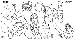
1. Remove the ABS wheel-speed sensor installation bolt, then remove the ABS wheel-speed sensor from the steering knuckle.
2. Remove the bolts and nuts shown in the figure, then disconnect the steering knuckle from the shock absorber.
am2zzw00003567
|
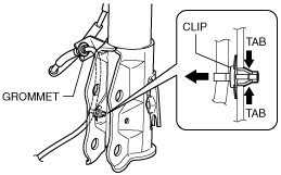
3. While pressing the tabs (2 locations) of the ABS wheel-speed sensor wiring harness clip, remove the ABS wheel-speed sensor wiring harness from the shock absorber.
am2zzw00003568
|
4. Remove the ABS wheel-speed sensor wiring harness grommet from the shock absorber.
5. Move the ABS wheel-speed sensor to a place out of the way.
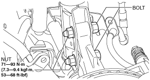
6. Install the steering knuckle to the shock absorber, insert the bolts from the direction shown as follows, then tighten them to the specified torque.
am2zzw00003569
|
Joint Shaft Removal Note
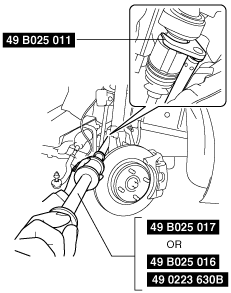
1. Disconnect the drive shaft (RH) from the joint shaft using the SSTs.
am2zzw00001452
|
2. Disconnect the joint shaft bracket from the cylinder block and remove the joint shaft.
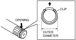
Clip Installation Note
1. Install a new clip onto the joint shaft with the opening facing upward.
2. After installation, measure the outer diameter.
am2zzw00001453
|
ABS Wheel-Speed Sensor Installation Note
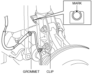
1. Install the ABS wheel-speed sensor wiring harness grommet to the shock absorber as shown in the figure.
am2zzw00003570
|
2. Install the ABS wheel-speed sensor wiring harness clip to the shock absorber.
3. Install the ABS wheel-speed sensor to the steering knuckle, then tighten the bolt (ABS wheel-speed sensor) to the specified torque.
4. Verify that the ABS wheel-speed sensor wiring harness is not twisted.