 |
am2zzw00003528
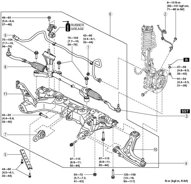
FRONT CROSSMEMBER REMOVAL/INSTALLATION
id021300125200
1. Remove the steering shaft cover. (See STEERING WHEEL AND COLUMN REMOVAL/INSTALLATION [L.H.D.].) (See STEERING WHEEL AND COLUMN REMOVAL/INSTALLATION [R.H.D.].)
2. Detach the intermediate shaft from the steering gear and linkage. (See STEERING WHEEL AND COLUMN REMOVAL/INSTALLATION [L.H.D.].) (See STEERING WHEEL AND COLUMN REMOVAL/INSTALLATION [R.H.D.].) (See STEERING GEAR AND LINKAGE REMOVAL/INSTALLATION.)
3. Remove in the order indicated in the table.
4. Install in the reverse order of removal.
5. Inspect the wheel alignment and adjust it if necessary. (See FRONT WHEEL ALIGNMENT.)
am2zzw00003528
|
|
1
|
Nut (lower end of stabilizer control link)
|
|
2
|
ABS wheel-speed sensor
|
|
3
|
Tie-rod end
(See Tie-rod End Removal Note.)
|
|
4
|
Front lower arm ball joint
|
|
5
|
Crossmember bracket (if equipped)
|
|
6
|
Crossmember component
|
|
7
|
No.1 engine mounting
|
|
8
|
Steering gear and linkage
|
|
9
|
Front stabilizer
|
|
10
|
Front lower arm
|
|
11
|
Front crossmember
|
ABS Wheel-Speed Sensor Removal Note
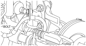
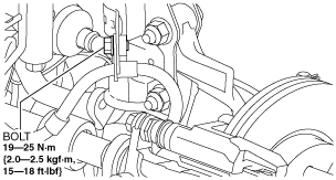
1. Remove the brake hose installation bolt shown in the figure, then remove the brake hose bracket from the shock absorber.
am2zzw00003529
|
2. Remove the ABS wheel-speed sensor installation bolt, then remove the ABS wheel-speed sensor from the steering knuckle.
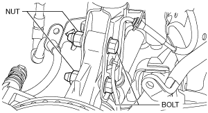
3. Remove the bolts and nuts shown in the figure, then disconnect the steering knuckle from the shock absorber.
am2zzw00003530
|
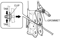
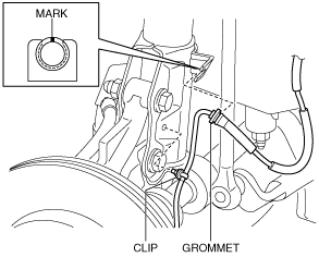
4. While pressing the tabs (2 locations) of the ABS wheel-speed sensor wiring harness clip, remove the ABS wheel-speed sensor wiring harness from the shock absorber.
am2zzw00003531
|
5. Remove the ABS wheel-speed sensor wiring harness grommet from the shock absorber.
6. Move the ABS wheel-speed sensor to a place out of the way.
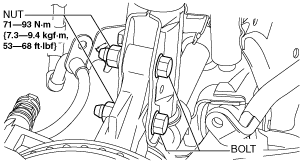
7. Install the steering knuckle to the shock absorber, insert the bolts from the direction shown as follows, then tighten them to the specified torque.
am2zzw00003564
|
8. Install the brake hose bracket to the shock absorber, then tighten the bolt to the specified torque.
am2zzw00003533
|
Tie-rod End Removal Note
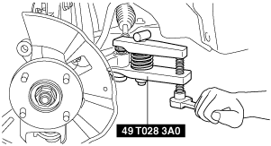
1. Remove the locknut of the tie-rod end.
2. Detach the tie-rod end from the steering knuckle using the SST.
am2zzw00002109
|
Crossmember Component Removal Note
1. Support the crossmember component using a jack.
am2zzw00001571
|
2. Detach the No.1 engine mounting from the engine. (See ENGINE REMOVAL/INSTALLATION [ZJ, ZY].) (See ENGINE REMOVAL/INSTALLATION [MZ-CD 1.4 DI Turbo].) (See ENGINE REMOVAL/INSTALLATION [MZ-CD 1.6 (Y6)].)
3. Remove the front crossmember installation bolts.
4. Lower the jack slowly and remove the front crossmember component.
Crossmember Component Installation Note
1. Support the crossmember component using a jack.
am2zzw00001571
|
2. Raise the jack slowly and install the front crossmember component.
3. Install the No.1 engine mounting (engine side). (See ENGINE REMOVAL/INSTALLATION [ZJ, ZY].) (See ENGINE REMOVAL/INSTALLATION [MZ-CD 1.4 DI Turbo].) (See ENGINE REMOVAL/INSTALLATION [MZ-CD 1.6 (Y6)].)
ABS Wheel-Speed Sensor Installation Note
1. Install the ABS wheel-speed sensor wiring harness grommet to the shock absorber as shown in the figure.
am2zzw00003534
|
2. Install the ABS wheel-speed sensor wiring harness clip to the shock absorber.
3. Install the ABS wheel-speed sensor to the steering knuckle, then tighten the bolt (ABS wheel-speed sensor) to the specified torque.
4. Verify that the ABS wheel-speed sensor wiring harness is not twisted.