DTC
C0061:01, C0061:28, C0061:64, C0063:01, C0063:28, C0063:64, C006A:16, C006A:17, C1108:01
Combined sensor system
DETECTION CONDITION
• C0061:01, C0063:01
-
― The voltage value from the combined sensor is not within specification.
• C0061:28, C0061:64
-
― Out-of-specification signal modulation or lateral-G value is detected from the combined sensor (lateral-G part).
• C0063:28, C0063:64
-
― Out-of-specification signal modulation or yaw rate value is detected from the combined sensor (yaw rate part).
• C006A:16, C006A:17
-
― Abnormal voltage to the combined sensor is detected.
• C1108:01
-
― The supply voltage of the combined sensor is not within specification.
POSSIBLE CAUSE
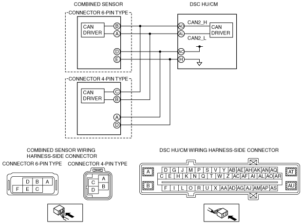
• Open or short circuit in the wiring harness between the following DSC HU/CM terminal and combined sensor terminal
-
― Combined sensor connector 6-pin type
-
• DSC HU/CM terminal AC—combined sensor terminal D
― Combined sensor connector 4-pin type-
• DSC HU/CM terminal AC—combined sensor terminal A
-
• Open or short circuit in the wiring harness between the following DSC HU/CM terminal and combined sensor terminal
-
― Combined sensor connector 6-pin type
-
• DSC HU/CM terminal H—combined sensor terminal E
― Combined sensor connector 4-pin type-
• DSC HU/CM terminal H—combined sensor terminal D
-
• Open circuit in the wiring harness between the following DSC HU/CM terminal and combined sensor terminal (CAN2 line)
-
― Combined sensor connector 6-pin type
-
• DSC HU/CM terminal AL—combined sensor terminal A
― Combined sensor connector 4-pin type-
• DSC HU/CM terminal AL—and combined sensor terminal B
-
• Open circuit in the wiring harness between the following DSC HU/CM terminal and combined sensor terminal (CAN2 line)
-
― Combined sensor connector 6-pin type
-
• DSC HU/CM terminal AO—combined sensor terminal B
― Combined sensor connector 4-pin type-
• DSC HU/CM terminal AO—combined sensor terminal C
-
• Combined sensor malfunction
• Poor connection at connectors (female terminal)