 |
am2zzw00001413
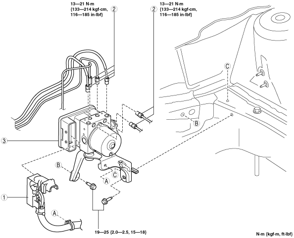
DSC HU/CM REMOVAL/INSTALLATION [R.H.D.]
id0415008010b5
1. Remove the battery, battery tray and battery tray bracket. (ZJ, ZY) (See BATTERY REMOVAL/INSTALLATION [ZJ, ZY].)
2. Remove the battery and battery tray. (MZ-CD 1.6 (Y6)) (See BATTERY REMOVAL/INSTALLATION [MZ-CD 1.6 (Y6)].)
3. Remove in the order indicated in the table.
4. Install in the reverse order of removal.
5. Add brake fluid, bleed the brakes, and inspect for leakage after the installation has been completed. (See AIR BLEEDING.)
6. Turn the ignition switch to the ON position or start the engine, and maintain this condition for approx. 30 s to allow the DSC HU/CM automatic configuration to be performed.
7. Perform the initialization procedures for the combined sensor, brake fluid pressure sensor. (See DSC SENSOR INITIALIZATION PROCEDURE.)
8. Perform the DTC inspection using the M-MDS. (See ON-BOARD DIAGNOSIS [DYNAMIC STABILITY CONTROL (DSC)].)
am2zzw00001413
|
|
1
|
Connector
(See Connector Removal Note.)
(See Connector Installation Note.)
|
|
2
|
Brake pipe
(See Brake Pipe Removal Note.)
(See Brake Pipe Installation Note.)
|
|
3
|
DSC HU/CM component
|
am2zzw00001414
|
|
1
|
Bracket
|
|
2
|
DSC HU/CM
|
|
3
|
DSC CM
|
|
4
|
DSC HU
|
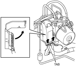
Connector Removal Note
1. Pull the connector cover up in the direction of the arrow while pressing the connector cover tab.
am2zzw00001327
|
2. Pull the connector toward the vehicle front and remove it.
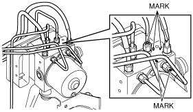
Brake Pipe Removal Note
1. Place an alignment mark on the brake pipe and DSC HU/CM.
am2zzw00001328
|
2. Affix protective tape to the connector to prevent brake fluid from entering.
3. Remove the brake pipe.
4. Adhere protective tape to the installation area of the DSC HU/CM brake pipe to prevent foreign material penetration.
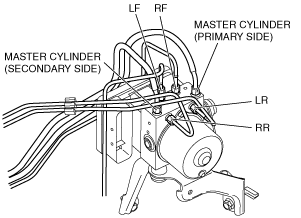
Brake Pipe Installation Note
1. Align the marks made before removal and install the brake pipe into the DSC HU/CM referring to the figure.
am2zzw00001329
|
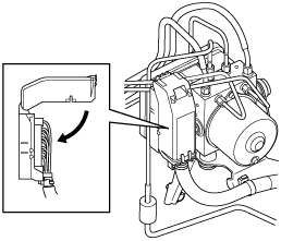
Connector Installation Note
1. After connecting the connector, verify that the connector cover is completely pushed in.
am2zzw00001330
|