STEP
INSPECTION
ACTION
1
VERIFY THAT THE ABS CM COMMUNICATION CONDITION TO OTHER MODULE
• Retrieve ABS DTC using the M-MDS.
• Is error message displayed regarding communication between ABS and M-MDS?
Yes
If a communication error message is displayed even after inspecting according to procedure displayed on M-MDS, go to Step 6.
No
Go to the next step.
2
INSPECT FOR DTCS IN ABS
• Retrieve ABS DTC using the M-MDS.
• Is there any ABS DTC displayed?
Yes
Go to applicable DTC troubleshooting procedure.
(See ON-BOARD DIAGNOSIS [ABS].)
No
Go to the next step.
3
INSPECT DTCS IN INSTRUMENT CLUSTER
• Retrieve instrument cluster DTC using the M-MDS.
• Is DTC U0415:92 displayed?
Yes
Go to the next step.
No
Go to Step 6.
4*
INSPECT ABS CM POWER SUPPLY VOLTAGE
• Monitor PID VPWR using the M-MDS data monitor function.
• Is the monitoring value above 10 V?
Yes
ABS CM internal malfunctions.
Replace the ABS CM.
No
Go to the next step.
5
INSPECT WHETHER IS IN INSTRUMENT CLUSTER OR ELSEWHERE
• Release the parking brake.
• Turn off all warning light and indicator light using M-MDS simulation function WL+IL?
• Does the ABS warning light turn off?
Yes
Go to the next step.
No
Replace the instrument cluster.
6
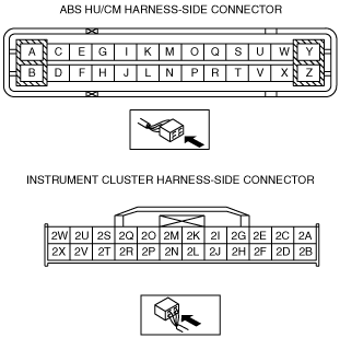
INSPECT FOR CONNECTION OF ABS HU/CM CONNECTOR
• Is the ABS HU/CM connector connected securely?
Yes
Go to Step 8.
No
Connect the connector securely, then go to the next step.
7
VERIFY ABS WARNING LIGHT OPERATION
• Turn the ignition switch to ON position.
• Does the ABS warning light turn off 4 seconds after the ignition switch is ON position?
Yes
Troubleshooting is completed. (ABS HU/CM connector is not connected securely.)
No
Go to the next step.
8
INSPECT BATTERY VOLTAGE
• Inspect battery voltage.
• Is the battery voltage normal?
Yes
Go to the next step.
No
Inspect charging system.
Replace the battery if necessary.
9
INSPECT BATTERY VOLTAGE WHILE ELECTRICAL LOAD IS OPERATING
• Inspect the battery voltage while electrical load (A/C, headlight etc.) is operating.
• Is the battery voltage normal?
Yes
Inspect wiring harness in ABS HU/CM terminal N and terminal B related circuit.
No
Inspect the charging system (drive belt tension, generator etc.).
