am2zzw00003836
|
MECHANICAL SYSTEM TEST
id051700802100
Mechanical System Test Preparation
1. Engage the parking brake and use wheel chocks at the front and rear of the wheels.
2. Inspect the engine coolant.
3. Inspect the engine oil.
4. Inspect the ATF. (See AUTOMATIC TRANSAXLE FLUID (ATF) INSPECTION.)
5. Inspect the idle speed.
6. Inspect the ignition timing.
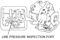
Line Pressure Test
1. Perform mechanical system test preparation. (See Mechanical System Test Preparation.)
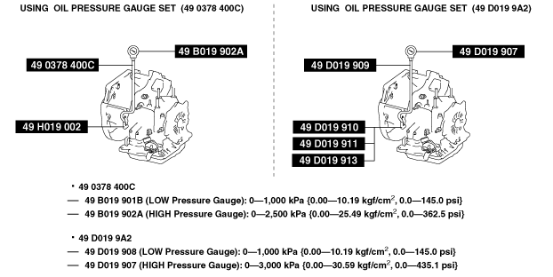
2. Perform the line pressure test at the engine idle speed for D range.
am2zzw00003836
|
am2zzw00003837
|
3. Perform the line pressure test at the engine idle speed for each position/range in the same manner.
4. Stop the engine.
5. Perform the line pressure test at engine stall speed for D range.
am2zzw00003838
|
6. Perform the line pressure test at the engine stall speed for each position/range in the same manner.
Line pressure
|
Position/Range |
Specification (kPa {kgf/cm2, psi}) |
|
|---|---|---|
|
D, S, L (Includes each HOLD mode)
|
Idle
|
330—470 {3.4—4.7, 48—68}
|
|
Stall
|
980—1,150 {10.0—11.7, 143—166}
|
|
|
R
|
Idle
|
490—710 {5.0—7.2, 71—102}
|
|
Stall
|
1,610—1,910 {16.5—19.4, 234—277}
|
|
Evaluation of line pressure test
|
Line pressure |
Possible cause |
|---|---|
|
Low pressure in all ranges
|
Worn oil pump
Oil leaking from oil pump, control valve body, and/or transaxle case
Pressure regulator valve sticking
Pressure control solenoid malfunction
Pressure modulator valve sticking
Solenoid reducing valve sticking
|
|
Low pressure in D and S only
|
Oil leaking from hydraulic circuit of forward clutch
|
|
Low pressure in L and R only
|
Oil leaking from hydraulic circuit of low and reverse brake
|
|
Low pressure in R only
|
Oil leaking from hydraulic circuit of reverse clutch
|
|
High pressure in all ranges
|
Pressure control solenoid malfunction
Pressure regulator valve sticking
Pressure modulator valve sticking
Pressure reducing valve sticking
|
7. Stop the engine.
8. Remove the SSTs.
9. Install a new square head plug in the inspection port.
Stall Test
1. Perform mechanical system test preparation. (See Mechanical System Test Preparation.)
2. Start the engine.
3. Perform the stall test for D range.
4. Perform the stall test for each position/range in the same manner.
Engine stall speed
|
Position/Range |
Specification (rpm) |
|---|---|
|
D, S, L (Includes each HOLD mode)
|
2,200—2,800
|
|
R
|
Evaluation of stall test
|
Condition |
Possible cause |
|
|---|---|---|
|
Above specification
|
Insufficient line pressure, torque converter pressure
|
• Worn oil pump
|
|
• Oil leaking from oil pump, control valve, and/or transaxle case
|
||
|
• Pressure regulator valve sticking
|
||
|
• Converter relief valve sticking
|
||
|
• Pressure control solenoid malfunction
|
||
|
In D range
|
• Forward clutch slipping
|
|
|
In S (HOLD) range
|
• 2-4 brake band slipping
|
|
|
In L (HOLD) range and R position
|
• Low and reverse brake slipping
|
|
|
In R position
|
• Low and reverse brake slipping
• Reverse clutch slipping
• Perform road test to determine whether problem is in low and reverse brake or reverse clutch
|
|
|
Below specification
|
• Engine lack of power
|
|
Time Lag Test
1. Perform mechanical system test preparation. (See Mechanical System Test Preparation.)
2. Start the engine.
3. Perform the time lag test when shifting the selector lever from N position to D range.
4. Perform the time lag test when shifting the selector lever from N position to R position in the same manner.
Evaluation of time lag test
|
Condition |
Possible Cause |
|
|---|---|---|
|
N → D shift
|
More than specification
|
Insufficient line pressure
Forward clutch slipping
Oil leaking from forward clutch fluid circuit
Shift solenoid A not operating properly
|
|
Less than specification
|
Forward accumulator not operating properly
Shift solenoid A not operating properly
Excessive line pressure
|
|
|
N → D (HOLD) shift*
|
More than specification
|
Insufficient line pressure
Forward clutch slipping
Shift solenoid A not operating properly
|
|
Less than specification
|
Forward accumulator not operating properly
Shift solenoid A not operating properly
Excessive line pressure
|
|
|
N → R shift
|
More than specification
|
Insufficient line pressure
Low and reverse brake slipping
Reverse clutch slipping
Shift solenoid B not operating properly
|
|
Less than specification
|
Servo apply accumulator not operating properly
Shift solenoid B not operating properly
Excessive line pressure
|
|