 |
adejjw00002888
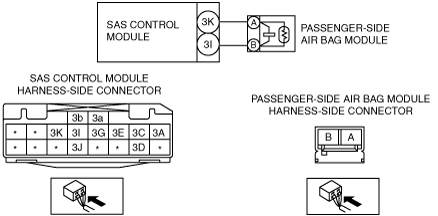
DTC B0010:1C
id080200825000
System Malfunction Location
Detection Condition
Possible Causes
System Wiring Diagram
adejjw00002888
|
Diagnostic Procedure
|
Step |
Inspection |
Action |
|
|---|---|---|---|
|
1
|
INSPECT PASSENGER-SIDE AIR BAG MODULE CONNECTOR
• Turn the ignition switch to the LOCK position.
• Disconnect the negative battery cable and wait for 1 min or more.
• Remove the glove compartment cover.
• Disconnect the passenger-side air bag module connector.
• Inspect the passenger-side air bag module connector. (Corrosion, damage, and disconnected pins)
• Is there any malfunction of the passenger-side air bag module connector?
|
Yes
|
Replace the passenger-side air bag module wiring harness.
|
|
No
|
Go to the next step.
|
||
|
2
|
INSPECT WIRING HARNESS BETWEEN SAS CONTROL MODULE AND PASSENGER-SIDE AIR BAG MODULE FOR SHORT TO BODY GROUND
• Remove the column cover.
• Disconnect the clock spring connector.
• Disconnect the driver and passenger-side side air bag module connectors.
• Remove the headliner.
• Disconnect the driver and passenger-side curtain air bag module connector.
• Disconnect the driver and passenger-side pre-tensioner seat belt connectors.
• Remove the rear console. (See REAR CONSOLE REMOVAL/INSTALLATION.)
• Disconnect the SAS control module connectors.
• Inspect for a continuity between SAS control module connector terminal 3K and body ground, SAS control module connector terminal 3I and body ground.
• Is there continuity?
|
Yes
|
Replace the wiring harness between the SAS control module and the passenger-side air bag module.
|
|
No
|
Go to the next step.
|
||
|
3
|
INSPECT THE WIRING HARNESS BETWEEN THE SAS CONTROL MODULE AND PASSENGER-SIDE AIR BAG MODULE FOR A SHORT CIRCUIT TO THE POWER SUPPLY
• Connect the negative battery cable.
• Turn the ignition switch to the ON position with SAS control module connector and passenger-side air bag module connector disconnected.
• Measure the voltage of SAS control module connector terminals 3K and 3I.
• Is the voltage measured?
|
Yes
|
Replace the wiring harness between the SAS control module and the passenger-side air bag module.
|
|
No
|
Go to the next step.
|
||
|
4
|
PERFORM SAS CONTROL MODULE DTC INSPECTION
• Turn the ignition switch to the LOCK position.
• Disconnect the negative battery cable and wait for 1 min or more.
• Reconnect all disconnected connectors.
• Connect the negative battery cable.
• Turn the ignition switch to the ON position
• Clear the DTC for the SAS control module using the M-MDS.
(See CLEARING DTC.)
• Perform the DTC inspection for the SAS control module using the M-MDS.
(See DTC DISPLAY.)
• Are the same DTCs present?
|
Yes
|
Replace the SAS control module.
|
|
No
|
DTC troubleshooting completed.
|
||