 |
am2zzw00003963
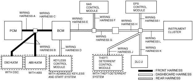
MODULE COMMUNICATION ERROR INSPECTION (R.H.D) [MULTIPLEX COMMUNICATION SYSTEM]
id0902e6038200
System Diagram
am2zzw00003963
|
Diagnostic Procedure
|
Step |
Inspection |
Action |
|
|---|---|---|---|
|
1
|
VERIFY MALFUNCTIONING PART DISPLAYED ON M-MDS
• Is “Fail” displayed on every unit?
|
Yes
|
Go to the next step.
|
|
No
|
Go to Step 6.
|
||
|
2
|
INSPECT DLC-2 CONNECTOR
• Is the DLC-2 connector normal?
|
Yes
|
Go to the next step.
|
|
No
|
Repair or replace the DLC-2 connector, then go to the next step.
|
||
|
3
|
INSPECT WIRING HARNESS M
• Inspect wiring harness K (CAN_L, CAN_H) for an open or short circuit (to ground and power supply system).
• Is the wiring harness normal?
|
Yes
|
Go to the next step.
|
|
No
|
Repair or replace wiring harness K, then go to the next step.
|
||
|
4
|
INSPECT PCM
• Disconnect the PCM connector.
• Measure the resistance between the following PCM connector terminal:
• Is the resistance 118—130 ohms?
|
Yes
|
Go to the next step.
|
|
No
|
Replace the PCM, then go to the next step.
|
||
|
5
|
INSPECT INSTRUMENT CLUSTER
• Disconnect the instrument cluster connector.
• Measure the resistance between the following instrument cluster connector terminal:
• Is the resistance 118—130 ohms?
|
Yes
|
Go to the next step.
|
|
No
|
Replace the instrument cluster, then go to the next step.
|
||
|
6
|
INSPECT WIRING HARNESS CONDITION OF EACH UNIT
• Determine the malfunctioning part referring to the table for determination. (See Determination.)
• Is the wiring harness normal?
|
Yes
|
Replace the malfunctioning unit, then perform the network test again.
|
|
No
|
Repair or replace the wiring harness, then perform the network test again.
|
||
Determination
|
PCM |
ABS HU/CM (with ABS), DSC HU/CM (with DSC) |
BCM |
Keyless control module |
SAS control module |
EPS control module |
Theft-deterrent control module |
Instrument cluster |
Malfunction location |
|---|---|---|---|---|---|---|---|---|
|
×
|
-
|
-
|
-
|
-
|
-
|
-
|
-
|
• Wiring harness A
• PCM
|
|
-
|
×
|
-
|
-
|
-
|
-
|
-
|
-
|
• Wiring harness B
• ABS HU/CM (with ABS)
• DSC HU/CM (with DSC)
|
|
×
|
×
|
-
|
-
|
-
|
-
|
-
|
-
|
• Wiring harness C
• PCM
• ABS HU/CM (with ABS)
• DSC HU/CM (with DSC)
|
|
-
|
-
|
-
|
×
|
-
|
-
|
-
|
-
|
• Wiring harness D
• Keyless control module
|
|
×
|
×
|
×
|
×
|
-
|
-
|
-
|
-
|
• Wiring harness E
• PCM
• ABS HU/CM (with ABS)
• DSC HU/CM (with DSC)
• BCM
• Keyless control module
|
|
-
|
-
|
-
|
-
|
×
|
-
|
-
|
-
|
• Wiring harness F
• SAS control module
|
|
×
|
×
|
×
|
×
|
×
|
-
|
-
|
-
|
• Wiring harness G
• Wiring harness H
• PCM
• ABS HU/CM (with ABS)
• DSC HU/CM (with DSC)
• BCM
• Keyless control module
• SAS control module
|
|
-
|
-
|
-
|
-
|
-
|
×
|
-
|
-
|
• Wiring harness I
• EPS control module
|
|
-
|
-
|
-
|
-
|
-
|
-
|
-
|
×
|
• Wiring harness L
• Instrument cluster
|