 |
am2zzw00002735
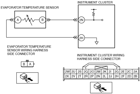
DTC B1B71:14 [INSTRUMENT CLUSTER]
id0902e8998900
|
DTC B1B71:14 |
Evaporator temperature sensor circuit malfunction |
|---|---|
|
Detection Condition
|
Evaporator temperature sensor resistance value not input for a continuous 5 s
|
|
Possible Causes
|
• Open or short to ground circuit in wiring harness between evaporator temperature sensor and instrument cluster
• Evaporator temperature sensor malfunction
• Instrument cluster malfunction
|
System Wiring Diagram
am2zzw00002735
|
Diagnostic Procedure
|
Step |
Inspection |
Action |
|
|---|---|---|---|
|
1
|
INSPECT EVAPORATOR TEMPERATURE SENSOR CONNECTOR CONDITION
• Turn the ignition switch to the LOCK position.
• Disconnect the evaporator temperature sensor connector.
• Inspect the connector and terminals (corrosion, damage, pin disconnection).
• Are the connector and terminals normal?
|
Yes
|
Go to the next step.
|
|
No
|
Repair/replace the connector or terminal.
After repair procedure, go to Step 9.
|
||
|
2
|
INSPECT EVAPORATOR TEMPERATURE SENSOR
• Inspect the evaporator temperature sensor.
• Is the evaporator temperature sensor normal?
|
Yes
|
Go to the next step.
|
|
No
|
Replace the evaporator temperature sensor.
After replacement, go to Step 9.
|
||
|
3
|
INSPECT EVAPORATOR TEMPERATURE SENSOR FOR SHORT CIRCUIT TO GROUND
• Inspect the wiring harness for continuity between evaporator temperature sensor connector terminal B and body ground.
• Is there continuity?
|
Yes
|
Repair/replace the malfunctioning vehicle wiring harness.
After repair procedure, go to Step 7.
|
|
No
|
Go to the next step.
|
||
|
4
|
INSPECT EVAPORATOR TEMPERATURE SENSOR FOR OPEN CIRCUIT
• Turn the ignition switch to the ON position.
• Measure the voltage at evaporator temperature sensor connector terminal B.
• Is the voltage 5 V?
|
Yes
|
Go to Step 8.
|
|
No
|
Go to the next step.
|
||
|
5
|
INSPECT EVAPORATOR TEMPERATURE SENSOR FOR OPEN CIRCUIT
• Measure the voltage at instrument cluster terminal 2N.
• Is the voltage 5 V?
|
Yes
|
Repair/replace the malfunctioning vehicle wiring harness.
After repair procedure, go to the next step.
|
|
No
|
Go to Step 8.
|
||
|
6
|
INSPECT EVAPORATOR TEMPERATURE SENSOR FOR OPEN CIRCUIT
• Turn the ignition switch to the LOCK position.
• Inspect the wiring harness for continuity between evaporator temperature sensor connector terminal A and body ground.
• Is there continuity?
|
Yes
|
Go to Step 9.
|
|
No
|
Go to the next step.
|
||
|
7
|
OPEN CIRCUIT IN EVAPORATOR TEMPERATURE SENSOR CIRCUIT
• Inspect for continuity between instrument cluster terminal 2H and body ground.
• Is there continuity?
|
Yes
|
Repair/replace the malfunctioning vehicle wiring harness.
After repair procedure, go to the next step.
|
|
No
|
Go to the next step.
|
||
|
8
|
VERIFY INSTRUMENT CLUSTER CONNECTOR CONDITION
• Disconnect the instrument cluster connector.
• Inspect the connector and terminals (corrosion, damage, pin disconnection).
• Are the connector and terminals normal?
|
Yes
|
Go to the next step.
|
|
No
|
Repair/replace the connector or terminal.
After repair procedure, go to the next step.
|
||
|
9
|
VERIFY THAT SAME DTC IS NOT OUTPUT AGAIN
• Reconnect the disconnected connectors.
• Clear the DTC.
• VERIFY DTCs.
• Is DTC B1B71:14 output?
|
Yes
|
Repeat the inspection from Step 1.
• If the malfunction does not recur, go to the next step.
• If the malfunction recurs, replace the instrument cluster.
|
|
No
|
Go to the next step.
|
||
|
10
|
VERIFY THAT NO OTHER DTCs ARE PRESENT
• Verify other DTC displayed.
• Are any other DTCs output?
|
Yes
|
Perform the corresponding DTC inspection.
|
|
No
|
DTC troubleshooting completed.
|
||