CONNECTING ROD CLEARANCE INSPECTION
id011000507600
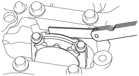
1. Measure the side clearance at the large end of the connecting rod using a feeler gauge.
-
• If it exceeds the maximum specification, replace the connecting rod or crankshaft.
-
Standard side clearance at the large end of connecting rod
-
0.14—0.36 mm {0.006—0.014 in}
-
Maximum side clearance at the large end of connecting rod
-
0.512 mm {0.0202 in}
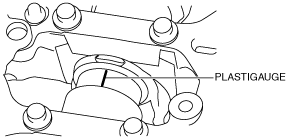
2. Measure the oil clearance at the large end of the connecting rod using the following procedure:
- (1) Cut the plastigauge as wide as the connecting rod bearing width, place it parallel to the crankshaft, keeping away from the oil hole.
-
- (2) Install the lower connecting rod bearing and connecting rod cap. (See CYLINDER BLOCK ASSEMBLY (I).)
- (3) Remove the connecting rod cap. (See CYLINDER BLOCK DISASSEMBLY (II).)
- (4) Measure the oil clearance at the large end of the connecting rod.
-
-
• If it exceeds the maximum specification, replace the bearing or grind the crank pin and use oversize bearings so that the specified clearance is obtained.
-
Standard bearing oil clearance at the large end of the connecting rod
-
0.026—0.052 mm {0.0011—0.0020 in}
-
Maximum bearing oil clearance at the large end of the connecting rod
-
0.10 mm {0.00394 in}
-
Connecting rod bearing size
-
STD: 1.501—1.520 mm {0.05910—0.05984 in}
OS 0.25: 1.626—1.633 mm {0.06402—0.06429 in}
OS 0.50: 1.751—1.758 mm {0.06894—0.06921 in}