 |
am2zzw00015005
HUB SPINDLE REMOVAL/INSTALLATION
id031200140400
1. Remove the ABS wheel-speed sensor. (See REAR ABS WHEEL-SPEED SENSOR REMOVAL/INSTALLATION.)
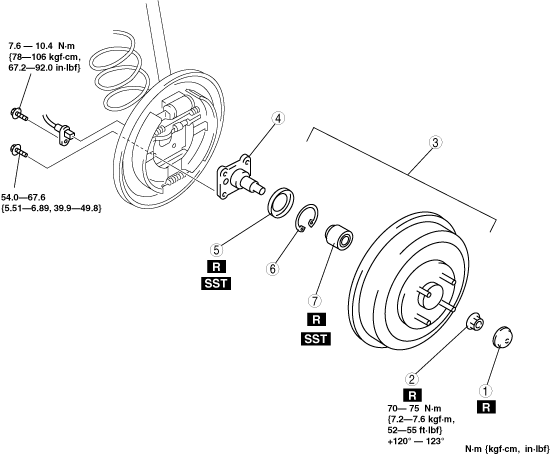
2. Remove in the order indicated in the table.
3. Install in the reverse order of removal.
am2zzw00015005
|
|
1
|
Hub cap
|
|
2
|
Locknut
|
|
3
|
Brake drum component
(See BRAKE DRUM REPLACEMENT)
|
|
4
|
Hub spindle
|
|
5
|
ABS sensor rotor
|
|
6
|
Clip
|
|
7
|
Wheel bearing
|
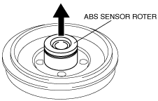
ABS Sensor Rotor Removal Note
1. Remove the ABS sensor rotor from the brake drum using a flathead screwdriver.
am2zzw00015006
|
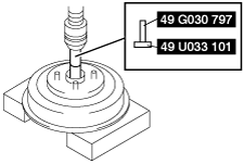
Wheel Bearing Removal Note
1. Remove the wheel bearing using the SSTs and press.
am2zzw00015007
|
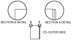
Wheel Bearing Installation Note
1. Set the wheel bearing to the brake drum as shown in the figure.
am2zzw00015008
|
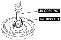
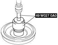
2. Install the wheel bearing using the SSTs and a press.
am2zzw00015009
|
ABS Sensor Rotor Installation Note
1. Put a new ABS sensor rotor in using the SSTs and a press.
am2zzw00015010
|
Locknut Installation Note
1. If dust or grease is on the hub spindle thread area, wipe it off with a cloth.
2. Tighten the locknut with 70—75 N·m {7.2—7.6 kgf·m, 52—55 ft·lbf} while turning the brake drum counterclockwise.
3. Turn the brake drum counterclockwise 10 times or more.
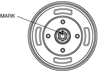
4. Mark the locknut and the hub spindle as shown in the figure.
am2zzw00015011
|
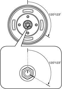
5. Tighten the locknut at the angle of 120—123 degrees while turning the brake drum to the left.
am2zzw00015012
|
6. Turn the brake drum slowly by hand, and verify that there is no noise or dragging/grinding feelings.