1. Remove the ABS wheel-speed sensor. (See FRONT ABS WHEEL-SPEED SENSOR REMOVAL/INSTALLATION.)
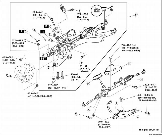
2. Remove in the order indicated in the table.
3. Install in the reverse order of removal.
4. After installation, inspect the front wheel alignment. (See FRONT WHEEL ALIGNMENT.)
|
1
|
Bolt (intermediate shaft)
|
|
2
|
Cotter pin
|
|
3
|
Nuts (tie-rod end)
|
|
4
|
Tie-rod end
(See Tie-rod End Removal Note)
|
|
5
|
Stabilizer control link (upper side)
|
|
6
|
Lower arm ball joint
|
|
7
|
Bolt (power steering oil pump)
|
|
8
|
Return hose
|
|
9
|
Bolt (No.1 engine mount)
|
|
10
|
Front crossmember, front stabilizer, lower arm and steering gear component
|
|
11
|
Insulator
|
|
12
|
Pressure pipe
|
|
13
|
Return pipe
(See Return Pipe Removal Note)
|
|
14
|
Dust cover
|
|
15
|
Steering gear and linkage
|
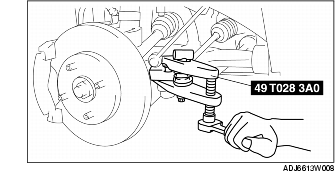
1. Remove the tie-rod end locknut.
2. Separate the tie-rod end from the steering knuckle using the SST.
1. Loosen the transaxle side No.1 engine mount installation bolt.
2. Remove the crossmember side No.1 engine mount installation bolt.
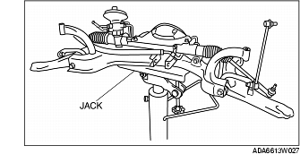
1. Remove the front crossmember, front stabilizer, lower arm and steering gear as a single unit using a jack.
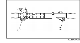
1. Mark the return pipe and steering gear for installation.
1. Loosely tighten bolts.
2. Tighten the mounting bracket bolts to the specified torque in the order shown.
Tightening torque
1. Install the front crossmember, front stabilizer, lower arm and steering gear as a single unit using a jack.
1. Install the crossmember side No.1 engine mount installation bolt.
2. Tighten the transaxle side No.1 engine mount installation bolt.
Tightening torque