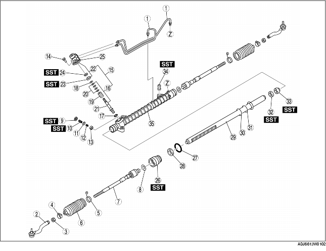
1. Disassemble in the order indicated in the table.
|
1
|
Oil pipe
|
|
2
|
Tie-rod end
|
|
3
|
Locknut
|
|
4
|
Boot clamp
|
|
5
|
Boot band
|
|
6
|
Boot
|
|
7
|
Tie rod
(See Tie Rod Disassembly Note)
|
|
8
|
Washer
|
|
9
|
Locknut (adjusting cover)
|
|
10
|
Adjusting cover
|
|
11
|
Spring washer
|
|
12
|
Yoke spring
|
|
13
|
Support yoke
|
|
14
|
Bolt
|
|
15
|
Pinion shaft and housing component
|
|
16
|
Pinion shaft component
|
|
17
|
O-ring
|
|
18
|
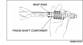
Snap ring
|
|
19
|
Control valve component
|
|
20
|
Seal ring
|
|
21
|
Pinion shaft
|
|
22
|
Valve housing component
|
|
23
|
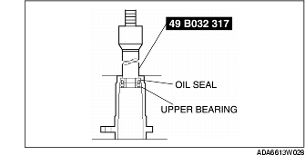
Upper bearing
|
|
24
|
Oil seal
|
|
25
|
Valve Housing
|
|
26
|
Holder
(See Holder Disassembly Note)
|
|
27
|
O-ring
|
|
28
|
U-gasket
|
|
29
|
Steering rack
|
|
30
|
Seal ring
|
|
31
|
O-ring
|
|
32
|
Oil seal
|
|
33
|
Inner guide
|
|
34
|
Mounting Rubber
|
|
35
|
Gear housing
|
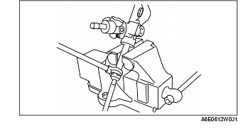
1. Unclamp the washer using a flathead screwdriver.
2. Remove the tie rod.
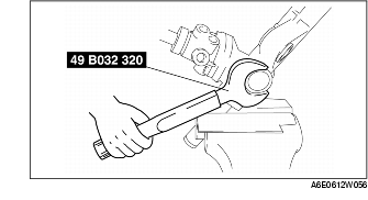
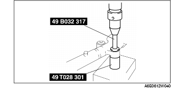
1. Remove the locknut using the SST.
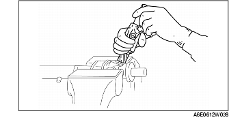
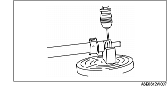
1. Hold the pinion shaft component as shown, and remove the pinion shaft and housing components.
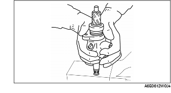
1. Push out the pinion shaft component from the valve housing component as shown.
1. Carefully remove the snap ring without damaging the pinion shaft component.
1. Set the SST as shown in the figure.
2. Using a press, remove the oil seal and upper bearing without applying pressure to the edge of the valve housing.
1. Cut away the staked areas of the bolt and cylinder using a drill.
2. Remove the holder.
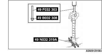
1. Install the SST (49 N032 319A) to the gear housing.
2. Insert the SSTs (49 F032 303, 49 B032 308) from the valve housing side.
3. Press out the oil seal and inner guide using a press.