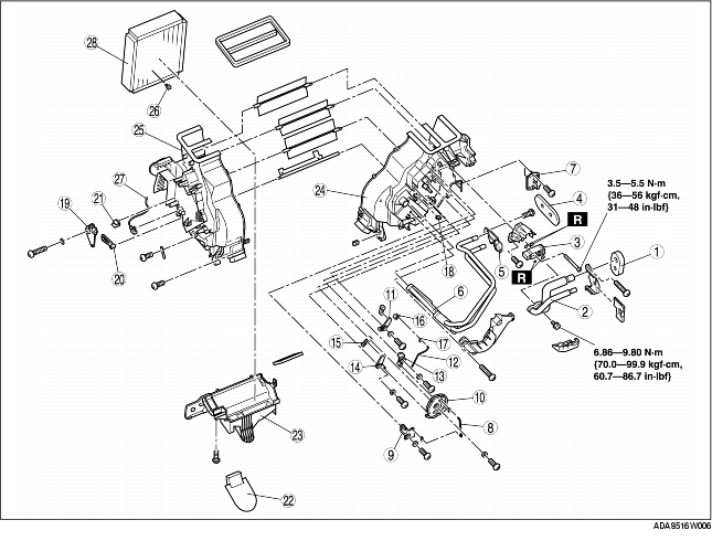
1. Disassemble in the order indicated in the table.
2. Assemble in the reverse order of disassembly.
|
1
|
Polyurethane foam (1)
|
|
2
|
Evaporator pipe
|
|
3
|
Expansion valve
|
|
4
|
Polyurethane foam (2)
|
|
5
|
Bracket
(See Bracket Removal Note)
|
|
6
|
Heater core
|
|
7
|
Resistor
|
|
8
|
Airflow mode rod (1)
|
|
9
|
Airflow mode sub link (4)
|
|
10
|
Airflow mode main link
|
|
11
|
Airflow mode sub link (1)
|
|
12
|
Airflow mode rod (2)
|
|
13
|
Airflow mode sub link (2)
|
|
14
|
Airflow mode sub link (3)
|
|
15
|
Airflow mode crank (1)
|
|
16
|
Airflow mode crank (2)
|
|
17
|
Airflow mode rod holder
|
|
18
|
Wire clamp
|
|
19
|
Air mix link
|
|
20
|
Air mix crank
|
|
21
|
Wire clamp
|
|
22
|
Adhesive polyurethane
|
|
23
|
A/C case (3)
|
|
24
|
A/C case (1)
|
|
25
|
A/C case (2)
|
|
26
|
Sensor clamp
|
|
27
|
Evaporator temperature sensor
|
|
28
|
Evaporator
|
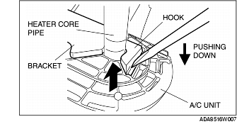
1. Insert a flathead screwdriver in the gap between the bracket hook and the A/C unit.
2. Remove the bracket by catching it with the flathead screwdriver tip and pushing down on the end of the flathead screwdriver.
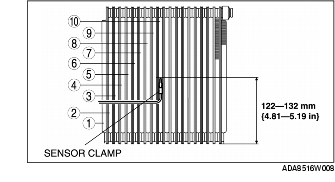
1. Assemble the evaporator temperature sensor as shown in the figure.
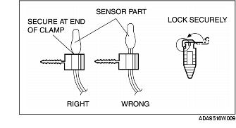
1. Attach the sensor clamp as shown in the figure.
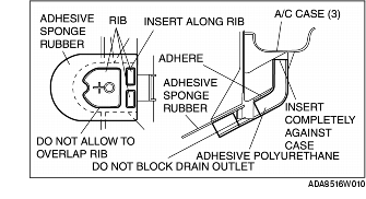
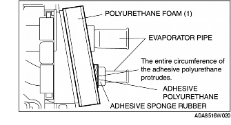
1. When installing new parts, attach adhesive sponge rubber and adhesive polyurethane as shown.
1. Assemble the polyurethane foam (1) as shown in the figure.