ON-BOARD DIAGNOSTIC FUNCTION
id094000101700
Outline
• The on-board diagnostic function is incorporated into the PCM, ABS HU/CM, and instrument cluster. This function can narrow down CAN system malfunction locations.
• The on-board diagnostic function consists of the following functions: a failure detection function, which detects malfunctions in CAN system-related parts; a memory function, which stores detected DTCs; a self-malfunction diagnostic function, which indicates system malfunctions using DTCs and warning lights; and a PID/data monitoring function, which verifies the input/output condition of specific input/output signals being read out.
• Using a WDS or equivalent, DTCs can be read out and deleted, and the PID/data monitoring function can be activated.
• The CAN system has a fail-safe function. When a malfunction occurs in CAN system, the transmission module sends a warning signal and the receiving module illuminates the warning light.
Block Diagram
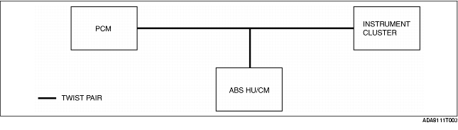
Failure detection function
• The failure detection function in each CAN system-related module detects malfunctions in input/output signals.
• This function outputs the DTC for the detected malfunction to the DLC-2, and also sends the detected result to the memory function and fail-safe function.
Fail-Safe Function
• When the failure detection function determines that there is a malfunction, the fail-safe function illuminates a warning light to advise the driver of the malfunction.
|
Module
|
Fail-safe function
|
|
PCM
|
• MIL illuminated
|
|
ABS HU/CM
|
• ABS suspended
• ABS warning light illuminated
|
|
Instrument cluster
|
• Speedometer, tachometer, water temperature gauge: 0 displayed
|
Memory Function
• The memory function stores the DTC for the malfunction of input/output signals for related parts, as determined by the failure detection function.
Self-Malfunction Diagnostic Function
• The self-malfunction diagnostic function determines that there is a malfunction, and outputs a signal, as a DTC, to the DLC-2. The DTC can be read out using a WDS or equivalent.
DTC table
|
DTC
|
Malfunction location
|
DTC output module
|
|
U0073
|
CAN system communication error
|
PCM
|
|
U0121
|
Communication error between the ABS HU/CM and DTC output unit
|
|
U0155
|
Communication error between the instrument cluster and DTC output unit
|
|
U1900
|
CAN system communication error
|
Instrument cluster
|
|
U2516
|
CAN system wiring harness open or short circuit
|
|
U2523
|
Communication error between the PCM and DTC output unit (Engine- related signal)
|
ABS HU/CM (Vehicles with ABS)
|
PID/Data Monitoring Function
• The PID/data monitoring function is used to freely select and read out, in real time, the monitored items for the input/output signals of the ABS HU/CM and instrument cluster.
• A WDS or equivalent is used to read out the PID/data monitor information.
|
PID name (definition)
|
WDS display
|
Detection state
|
PID monitor module
|
Terminal
|
|
ABS_MSG
(Signal reception error from the ABS HU/CM)
|
Present
|
Circuit between the ABS HU/CM and monitor module is normal.
|
Instrument cluster
|
Instrument cluster:
2W, 2X
|
|
Not Present
|
Circuit between the ABS HU/CM and monitor module is abnormal.
|
|
PCM_MSG
(Signal reception error from PCM)
|
Present
|
Circuit between the PCM and monitor module is normal.
|
|
Not Present
|
Circuit between the PCM and monitor module is abnormal.
|
Narrowing Down Malfunction Locations
• The on-board diagnostic function can narrow down a CAN system malfunction location by verifying the detected DTC and PID/data monitor information from each module. Refer to the Self-Malfunction Diagnostic Function and PID/Data Monitoring Function for detailed information regarding DTCs and the PID/data monitor. (See Self-Malfunction Diagnostic Function.) (See PID/Data Monitoring Function.)
Flowchart
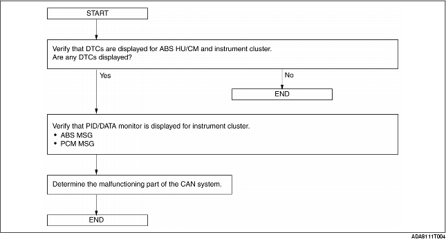
Example (PCM-related communication error)
1. DTCs for the PCM, ABS HU/CM and instrument cluster can be verified using a WDS or equivalent.
|
Module
|
Displayed DTC
|
Probable malfunction location
|
|
PCM
|
U0073
|
PCM-related CAN system malfunction
|
|
U0121
|
Communication error between PCM and ABS HU/CM
|
|
U0155
|
Communication error between PCM and instrument cluster
|
|
ABS HU/CM
|
U2523
|
Communication error between PCM and ABS HU/CM
|
|
Instrument cluster
|
U1900, U2516
|
Instrument cluster-related CAN system malfunction
|
2. PID/data monitor information for the instrument cluster can be verified using a WDS or equivalent.
|
Module
|
PID name (definition)
|
Condition
|
Probable malfunction point
|
|
Instrument cluster
|
PCM_MSG
(Missing message from the PCM)
|
Not Present
|
Communication error between instrument cluster and PCM
|
|
ABS_MSG
(Missing message from the ABS HU/CM)
|
Present
|
Normal communication between instrument cluster and ABS HU/CM
|
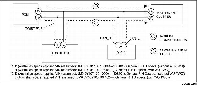
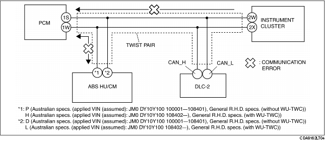
3. If there is a communication error between the ABS HU/CM and PCM, or between the instrument cluster and PCM, even if the communication between the ABS HU/CM and the instrument cluster is normal, it is probable that there is a malfunction in the PCM or PCM-related wiring harnesses.