 |
bezeze00000079
CYLINDER BLOCK ASSEMBLY (I)
id011000504000
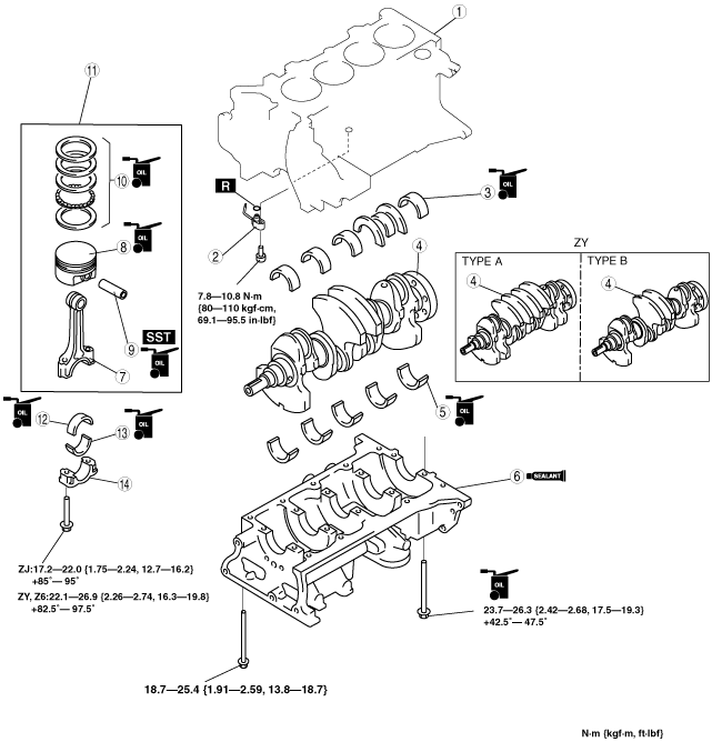
1. Assemble in the order indicated in the table.
bezeze00000079
|
|
1
|
Upper cylinder block
|
|
2
|
Oil jet valve
|
|
3
|
Upper main bearing
|
|
4
|
Crankshaft
|
|
5
|
Lower main bearing
|
|
6
|
Lower cylinder block
|
|
7
|
Connecting rod
|
|
8
|
Piston
(See Piston Assembly Note)
|
|
9
|
Piston pin
(See Piston Pin Assembly Note)
|
|
10
|
Piston ring
|
|
11
|
Piston, connecting rod
|
|
12
|
Upper connecting rod bearing
|
|
13
|
Lower connecting rod bearing
|
|
14
|
Connecting rod cap
|
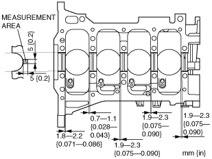
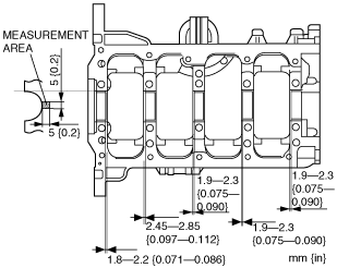
Main Bearing Assembly Note
1. Assemble the upper and lower main bearing as specified shown in the figure.
bezeze00000080
|
bezeze00000081
|
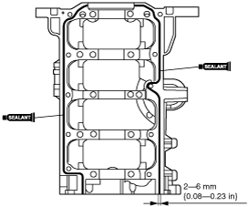
Lower Cylinder Block Assembly Note
1. Apply silicone sealant to the lower cylinder block attachment side as shown in the figure.
bezeze00000082
|
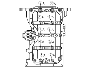
2. Apply clean engine oil to the lower cylinder block installation bolts A.
3. Tighten the lower cylinder block installation bolts A in two steps in the order shown in the figure.
bezeze00000083
|
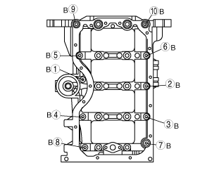
4. Tighten the lower cylinder block installation bolts B in the order shown in the figure.
bezeze00000084
|
5. Loosen bolts A and tighten the lower cylinder block installation bolts in two steps in the order shown a second time.
bezeze00000083
|
Piston Assembly Note
bezeze00000085
|
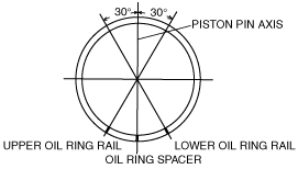
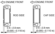
1. Position the end gap of each oil ring as shown in the figure.
bezeze00000086
|
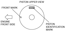
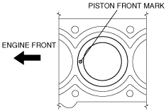
2. Insert the piston into the cylinder with the mark on top of the piston facing the front of the engine.
bezeze00000087
|
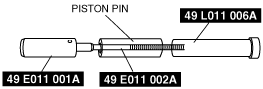
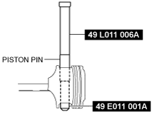
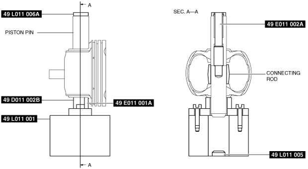
Piston Pin Assembly Note
1. Assemble the SSTs as shown in the figure.
bezuue00000063
|
bezuue00000138
|
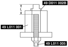
2. Assemble the SST (49 D011 002B) and the SST (49 L011 005) to the SST (49 L011 011).
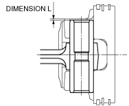
3. Adjust the SST (49 L011 005) and adjust dimension L shown in the figure to the following values.
bezuue00000064
|
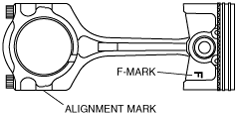
4. Assemble the connecting rod and piston to insert the piston pin. At this time, point the alignment mark on the connecting rod and the F mark on the piston in the same direction.
bezuue00000065
|
5. Insert the piston pin assembled with the SSTs into the piston and connecting rod.
bezuue00000146
|
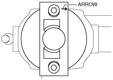
6. Set the SSTs as shown in the figure. At this time, point the piston head in the direction of the arrow on the SST (49 D011 002B) and align the piston hole position with the SST hole position. In addition, set the piston on the SST (49 D011 002B) horizontally.
bezuue00000143
|
bezuue00000144
|
7. Press fit the piston pin until the lower end of the SST (49 E011 001A) contacts the SST (49 L011 005) using a hydraulic press.
8. Inspect dimension L shown in the figure.
bezuue00000145
|
Piston pin re-assembly procedure
1. Press out the piston pin. (See CYLINDER BLOCK DISASSEMBLY (II).)
2. Press fit the piston pin again according to the [Piston Pin Assembly Note] procedures. However, correct dimension L of the SST. (See Piston Pin Assembly Note.)
Piston Ring Assembly Note
1. Assemble the oil ring.
bezeze00000088
|
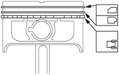
2. Install the second ring with the notch facing downward.
3. Install the top ring with scraper face side upward.
Connecting Rod Bearing Assembly Note
1. Install the connecting rod bearing to the connecting rod and the connecting rod cap as specified shown in the figure.
bezeze00000089
|
Connecting Rod Cap Assembly Note
1. Install the connecting rod cap with the knock pins and the alignment marks aligned.
2. Tighten the connecting rod cap installation bolt in two steps.