1. Perform the preinspeciton before disassembly. (See Differential Preinspection.)
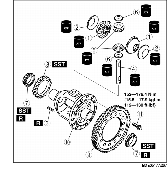
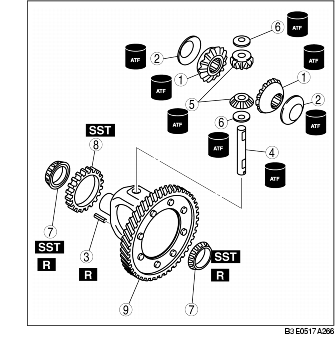
2. Disassemble in the order indicated in the table.
3. Assemble in the reverse order of disassembly.
RIVET FIXED TYPE
.
|
1
|
Side gear
|
|
2
|
Thrust washer
|
|
3
|
Roll pin
(See Roll Pin Disassembly Note.)
|
|
4
|
Pinion shaft
|
|
5
|
Pinion gear
|
|
6
|
Thrust washer
|
|
7
|
Bearings
(See Bearings Disassembly Note.)
|
|
8
|
Sensor rotor
|
|
9
|
Ring gear and gear case
|
BOLT FIXED TYPE
.
|
1
|
Side gear
|
|
2
|
Thrust washer
|
|
3
|
Roll pin
(See Roll Pin Disassembly Note.)
|
|
4
|
Pinion shaft
|
|
5
|
Pinion gear
|
|
6
|
Thrust washer
|
|
7
|
Bearings
(See Bearings Disassembly Note.)
|
|
8
|
Sensor rotor
|
|
9
|
Ring gear
|
|
10
|
Gear case
|
|
11
|
Bolt
|
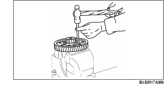
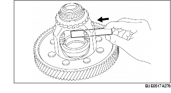
1. Place the gear case in a vise.
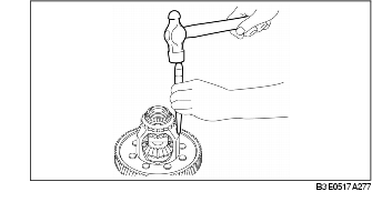
2. Insert a 2.0 mm {0.07 in} punch into the roll pin hole from the ring gear side, and remove the roll pin.
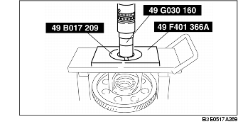
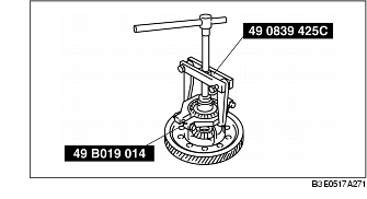
1. Remove the bearing (speedometer drive gear side) from the gear case using the SSTs.
2. Remove the bearing (ring gear side) from the gear case using the SST.
1. Install the ring gear to the gear case. (bolt fixed type)
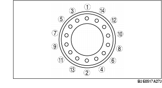
2. Tighten the bolts evenly and gradually in the order shown. (bolt fixed type)
Tightening torque
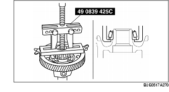
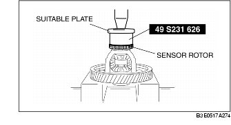
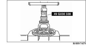
3. Install the sensor rotor to the gear case using the SST and suitable plate.
4. Install a new bearing.
5. Apply ATF to the thrust washers and pinion shaft.
6. Install the pinion gear and thrust washers into the gear case.
7. Install the pinion shaft.
8. Install the roll pin, and crimp it to prevent it from coming out of the gear case.
9. Apply ATF to the thrust washers.
10. Install the thrust washers and side gears into the gear case, then turn the side gears and align them with the drive shaft holes.
11. Measure the backlash of the side gears as follows: