DTC P0571:00 [MZR 1.3, MZR 1.5]
id0102f8705500
DTC P0571:00 |
Brake switch circuit problem |
---|---|
DETECTION CONDITION
|
• The PCM monitors switching in conjunction with brake switches No.1 and No.2. If either No.1 or No.2 do not switch for a continuous five times even though either No.1 or No.2 is switched from off to on or from on to off, P0571:00 is detected.
Diagnostic support note
• This is a continuous monitor (other).
• The MIL does not illuminate.
• FREEZE FRAME DATA (Mode 2)/Snapshot data is not available.
• The DTC is stored in the PCM memory.
|
POSSIBLE CAUSE
|
• Brake switch connector or terminals malfunction
• Short to ground or open circuit in brake switch No.1 power supply circuit
• Open circuit in wiring harness between brake switch terminal C and body ground (ATX, CVT)
• Open circuit in wiring harness between brake switch terminal B and body ground (MTX)
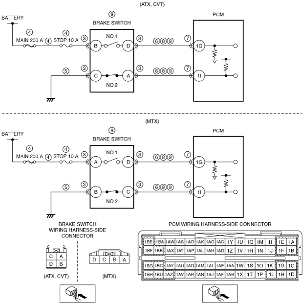
• Short to ground in wiring harness between the following terminals:
• PCM connector or terminals malfunction
• Short to power supply in wiring harness between the following terminals:
• Open circuit in wiring harness between the following terminals:
• Brake switch malfunction
• PCM malfunction
|
![]() |
Diagnostic procedure
STEP |
INSPECTION |
ACTION |
|
---|---|---|---|
1
|
VERIFY RELATED SERVICE INFORMATION AVAILABILITY
• Verify related Service Information availability.
• Is any related Service Information available?
|
Yes
|
Perform repair or diagnosis according to the available Service Information.
• If the vehicle is not repaired, go to the next step.
|
No
|
Go to the next step.
|
||
2
|
VERIFY RELATED PENDING CODE AND/OR DTC
• Turn the ignition switch off, then to the ON position (engine off).
• Perform the Pending Trouble Code Access Procedure and DTC Reading Procedure.
• Is the PENDING CODE/DTC P0703:00 also present?
|
Yes
|
Go to the applicable PENDING CODE or DTC inspection.
|
No
|
Go to the next step.
|
||
3
|
INSPECT BRAKE SWITCH CONNECTOR CONDITION
• Turn the ignition switch off.
• Disconnect the brake switch connector.
• Inspect for poor connection (such as damaged/pulled-out pins, corrosion).
• Is there any malfunction?
|
Yes
|
Repair or replace the connector and/or terminals, then go to Step 10.
|
No
|
Go to the next step.
|
||
4
|
INSPECT BRAKE SWITCH NO.1 POWER SUPPLY CIRCUIT FOR SHORT TO GROUND OR OPEN CIRCUIT
• Brake switch connector is disconnected.
• Measure the voltage at the brake switch terminal B (wiring harness-side). (ATX, CVT)
• Measure the voltage at the brake switch terminal A (wiring harness-side). (MTX)
• Is the voltage B+?
|
Yes
|
Go to the next step.
|
No
|
Inspect the MAIN 200 A fuse and STOP 10 A fuse.
• If the fuse is melted:
• If the fuse is deteriorated:
• If all fuses are normal:
Go to Step 10.
|
||
5
|
INSPECT BRAKE SWITCH NO.2 GROUND CIRCUIT FOR OPEN CIRCUIT
• Brake switch connector is disconnected.
• Inspect for continuity between brake switch terminal C (wiring harness-side) and body ground. (ATX, CVT)
• Inspect for continuity between brake switch terminal B (wiring harness-side) and body ground. (MTX)
• Is there continuity?
|
Yes
|
Go to the next step.
|
No
|
Repair or replace the wiring harness for a possible open circuit, then go to Step 10.
|
||
6
|
INSPECT BRAKE SWITCH CIRCUIT FOR SHORT TO GROUND
• Brake switch connector is disconnected.
• Inspect for continuity between the following terminals (wiring harness-side) and body ground:
• Is there continuity?
|
Yes
|
If the short to ground circuit could be detected:
• Repair or replace the wiring harness for a possible short to ground.
If the short to ground circuit could not be detected:
• Replace the PCM (short to ground in the PCM internal circuit).
Go to Step 10.
|
No
|
Go to the next step.
|
||
7
|
INSPECT PCM CONNECTOR CONDITION
• Disconnect the PCM connector.
• Inspect for poor connection (such as damaged/pulled-out pins, corrosion).
• Is there any malfunction?
|
Yes
|
Repair or replace the connector and/or terminals, then go to Step 10.
|
No
|
Go to the next step.
|
||
8
|
INSPECT BRAKE SWITCH CIRCUIT FOR SHORT TO POWER SUPPLY
• Brake switch and PCM connectors are disconnected.
• Turn the ignition switch to the ON position (engine off).
• Measure the voltage at the following terminals (wiring harness-side):
• Is there any voltage?
|
Yes
|
Repair or replace the wiring harness for a possible short to power supply, then go to Step 10.
|
No
|
Go to the next step.
|
||
9
|
INSPECT BRAKE SWITCH CIRCUIT FOR OPEN CIRCUIT
• Brake switch and PCM connectors are disconnected.
• Turn the ignition switch off.
• Inspect for continuity between the following terminals (wiring harness-side):
• Is there continuity?
|
Yes
|
Replace the brake switch, then go to the next step.
|
No
|
Repair or replace the wiring harness for a possible open circuit, then go to the next step.
|
||
10
|
VERIFY DTC TROUBLESHOOTING COMPLETED
• Make sure to reconnect all disconnected connectors.
• Clear the DTC from the PCM memory using the M-MDS.
• Turn the ignition switch to the ON position (engine off).
• Depress and release the brake pedal more than 5 times.
• Perform the DTC Reading Procedure.
• Is the same DTC present?
|
Yes
|
Repeat the inspection from Step 1.
• If the malfunction recurs, replace the PCM.
Go to the next step.
|
No
|
Go to the next step.
|
||
11
|
VERIFY AFTER REPAIR PROCEDURE
• Perform the “AFTER REPAIR PROCEDURE”.
• Are any DTCs present?
|
Yes
|
Go to the applicable DTC inspection.
(See DTC TABLE [MZR 1.3, MZR 1.5].)
|
No
|
DTC troubleshooting completed.
|