 |
am2zzw00006999
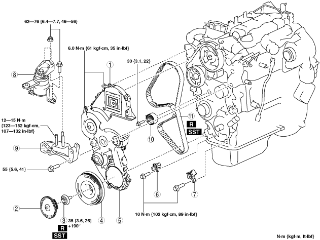
TIMING BELT REMOVAL/INSTALLATION [MZ-CD 1.6]
id0110e3804000
1. Disconnect the negative battery cable.
2. Remove the following parts:
3. Set the cooler hose (LO) out of the way. (See REFRIGERANT LINE REMOVAL/INSTALLATION [MZ-CD 1.6].)
4. Remove the wiring harness.
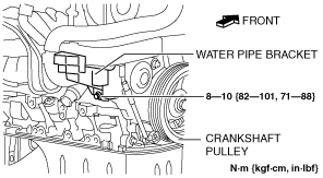
5. Remove the water pipe bracket installation bolt and set the water pipe bracket out of the way.
am2zzw00006999
|
6. Remove in the order indicated in the table.
7. Install in the reverse order of removal.
8. Start the engine.
9. Inspect the pulley and belt for runout and contact and adjust them if necessary.
am2zzw00006309
|
|
1
|
Upper timing belt cover
|
|
2
|
Crankshaft pulley cover
|
|
3
|
Crankshaft pulley installation bolt
|
|
4
|
Crankshaft pulley
|
|
5
|
Lower timing belt cover
|
|
6
|
CKP sensor
|
|
7
|
Timing belt guide
|
|
8
|
No.3 engine mount rubber
|
|
9
|
No.3 engine mount bracket
|
|
10
|
Timing belt tensioner
|
|
11
|
Timing belt
|
Crankshaft Pulley Installation Bolt Removal Note
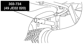
1. Lock the flywheel using the SST.
am2zzw00007000
|
Crankshaft pulley Removal Note
No.3 Engine Mount Rubber Removal Note
am2zzw00007001
|
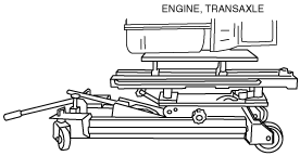
1. Secure the engine and the transaxle using an engine jack.
am2zzw00007002
|
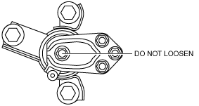
Timing Belt Tensioner, Timing Belt Removal Note
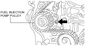
1. Tighten the crankshaft pulley installation bolt to secure the timing belt pulley.
2. Align the timing belt pulley using the SST.
am2zzw00007003
|
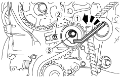
3. Align the camshaft pulley using the SST.
am2zzw00006358
|
4. Remove the timing belt tensioner.
5. Remove the timing belt.
Timing Belt Tensioner, Timing Belt Installation Note
1. Align a timing belt tensioner with the installation position and temporarily tighten the timing belt tensioner installation bolt by hand.
2. Install the new timing belt.
3. Tension the timing belt using the following steps.
am2zzw00007004
|
4. Remove the SST.
am2zzw00007003
|
5. Remove the SST.
am2zzw00006358
|
6. Rotate the crankshaft 10 revolutions.
7. Install the SST.
am2zzw00007003
|
8. Install the SST.
am2zzw00006358
|
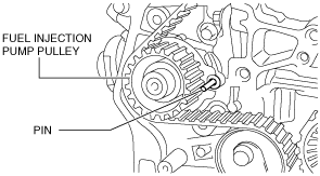
9. Insert the pin (commercially-available: 6 mm diameter) into the hole shown in the figure.
am2zzw00006359
|
10. Remove the SST.
am2zzw00006358
|
11. Remove the SST.
am2zzw00007003
|
12. Remove the pin (commercially-available: 6 mm diameter) shown in the figure.
am2zzw00007005
|
13. Discard the crankshaft pulley installation bolt.
No.3 Engine Mount Rubber Installation Note
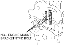
1. Tighten the No. 3 engine mount bracket stud bolts.
am2zzw00007006
|
2. Secure the engine and the transaxle using an engine jack.
am2zzw00007007
|
3. Install the No.3 engine mount, and then temporarily tighten the installation bolts and nuts.
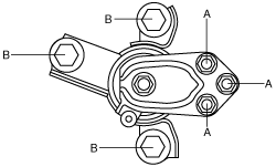
4. Tighten the installation nuts and bolts by order of A, B.
am2zzw00007008
|
Crankshaft Pulley Installation Bolt Installation Note
1. Lock the flywheel using the SST.
am2zzw00007000
|
2. Tighten the crankshaft pulley installation bolt using the SST (49 D032 316) in two steps.