 |
am2zzw00001388
FRONT SHOCK ABSORBER AND COIL SPRING DISASSEMBLY/ASSEMBLY
id021300121900
1. Remove the front shock absorber and coil spring. (See FRONT SHOCK ABSORBER AND COIL SPRING REMOVAL/INSTALLATION.)
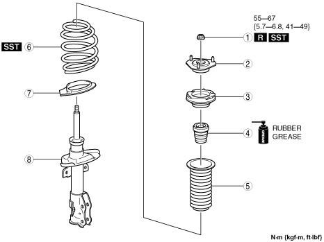
2. Disassemble in the order indicated in the table.
3. Assemble in the reverse order of removal.
4. Inspect the wheel alignment and adjust it if necessary. (See FRONT WHEEL ALIGNMENT.)
am2zzw00001388
|
|
1
|
Piston rod nut
(See Piston Rod Nut Assembly Note.)
|
|
2
|
Mounting rubber
|
|
3
|
Bearing
|
|
4
|
Bound stopper
|
|
5
|
Dust boot
|
|
6
|
Coil spring
(See Coil Spring Assembly Note.)
|
|
7
|
Lower spring seat
|
|
8
|
Front shock absorber
|
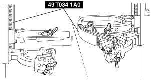
Piston Rod Nut Disassembly Note
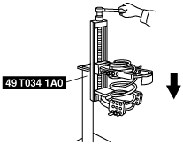
1. Install the coil spring to the SST using the following procedure.
am2zzw00002927
|
am2zzw00002928
|
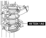
2. Compress the coil spring using the SST.
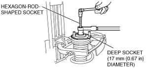
3. Remove the piston rod nut using the following tools.
am2zzw00001385
|
am2zzw00001804
|
Coil Spring Assembly Note
1. Compress the coil spring using the SST.
ampjjw00000536
|
2. Install the shock absorber with the lower end of the coil spring seated on the step of the lower spring seat.
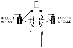
Bound Stopper Assembly Note
1. Apply the rubber grease to the contact surface of the bound stopper and bearing, and the inside of the bound stopper indicated in the figure.
am2zzw00001628
|
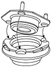
Mounting Rubber Assembly Note
1. Align the bolt heads of the mounting rubber stud bolt with the hollows in the upper spring seat, and assemble.
am2zzw00003272
|
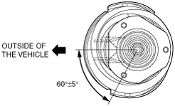
2. Install the mounting rubber so that the angle of the mounting rubber stud and the center of the shock absorber bracket is 60°±5°.
am2zzw00006242
|
Piston Rod Nut Assembly Note
1. Install the piston rod nut using the following tools.
am2zzw00001385
|
am2zzw00001804
|