|
am2zzw00003642
DRIVE SHAFT REMOVAL/INSTALLATION [MZR1.3, MZR 1.5]
id0313008019k3
1. Drain the transaxle oil or ATF. (See TRANSAXLE OIL REPLACEMENT [F35M-R].) (SeeAUTOMATIC TRANSAXLE FLUID (ATF) REPLACEMENT [FN4A-EL].)
2. Remove in the order indicated in the table.
3. Install in the reverse order indicated in the table.
4. Add the transaxle oil or ATF. (See TRANSAXLE OIL REPLACEMENT [F35M-R].) (See AUTOMATIC TRANSAXLE FLUID (ATF) REPLACEMENT [FN4A-EL].)
am2zzw00003642
|
|
1
|
Nut (stabilizer control link upper side)
|
|
2
|
Bolt (brake hose bracket)
|
|
3
|
Tie-rod end
|
|
4
|
ABS wheel-speed sensor
|
|
5
|
Locknut
|
|
6
|
Front lower arm ball joint
|
|
7
|
Clip
|
|
8
|
Drive shaft
(See Drive Shaft Removal Note.)
|
|
9
|
Clip
(See Clip Installation Note.)
|
ABS Wheel-Speed Sensor Removal Note
1. Remove the ABS wheel-speed sensor installation bolt, then remove the ABS wheel-speed sensor from the steering knuckle.
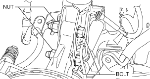
2. Remove the bolts and nuts shown in the figure, then disconnect the steering knuckle from the shock absorber.
am2zzw00003544
|
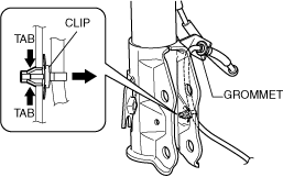
3. While pressing the tabs (2 locations) of the ABS wheel-speed sensor wiring harness clip, remove the ABS wheel-speed sensor wiring harness from the shock absorber.
am2zzw00003545
|
4. Remove the ABS wheel-speed sensor wiring harness grommet from the shock absorber.
5. Move the ABS wheel-speed sensor to a place out of the way.
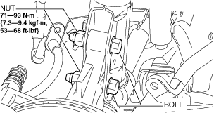
6. Install the steering knuckle to the shock absorber, insert the bolts from the direction shown as follows, then tighten them to the specified torque.
am2zzw00003564
|
Drive Shaft Removal Note
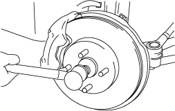
1. Install a spare nut onto the drive shaft so that the nut is flush with the end of the drive shaft.
2. Tap the nut with a copper hammer to loosen the drive shaft from the front wheel hub.
avejjw00001200
|
3. Separate the drive shaft from the wheel hub.
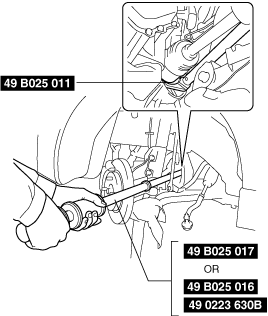
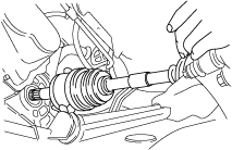
4. Separate the LH drive shaft from the transaxle using the SSTs as shown in the figure.
am2zzw00001478
|
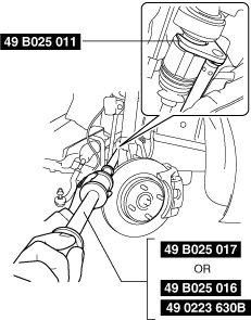
5. Remove the RH drive shaft from the joint shaft using the SSTs.
am2zzw00001479
|
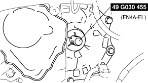
6. Install the SST to the transaxle after the drive shaft is removed.
am2zzw00007049
|
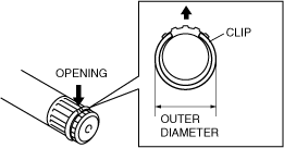
Clip Installation Note
1. Install a new clip onto the joint shaft with the opening facing upward. Ensure that the diameter of the clip does not exceed the specification on installation.
am2zzw00001480
|
Drive Shaft Installation Note
LH side
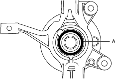
1. Apply grease (D4Y0 33247) to the wheel bearing inner race and drive shaft contact surface (Area A in figure).
adejjw00005000
|
2. Insert the drive shaft into the wheel hub.
3. Apply transaxle oil or ATF to the oil seal lip.
4. Push the drive shaft into the transaxle.
am2zzw00001481
|
5. After installation, pull the transaxle side outer ring forward to confirm that the drive shaft is securely held by the clip.
RH side
1. Install a new clip to the joint shaft. (See JOINT SHAFT REMOVAL/INSTALLATION [MZR1.3, MZR 1.5].)
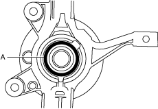
2. Apply grease (D4Y0 33247) to the wheel bearing inner race and drive shaft contact surface (Area A in figure).
adejjw00005002
|
3. Insert the drive shaft to the wheel hub.
4. Insert the drive shaft to the joint shaft.
5. After installation, pull the transaxle side outer ring forward to confirm that the drive shaft is securely held by the clip.
ABS Wheel-Speed Sensor Installation Note
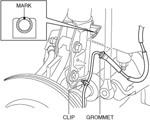
1. Install the ABS wheel-speed sensor wiring harness grommet to the shock absorber as shown in the figure.
am2zzw00003547
|
2. Install the ABS wheel-speed sensor wiring harness clip to the shock absorber.
3. Install the ABS wheel-speed sensor to the steering knuckle, then tighten the bolt (ABS wheel-speed sensor) to the specified torque.
4. Verify that the ABS wheel-speed sensor wiring harness is not twisted.