 |
am2zzw00005513
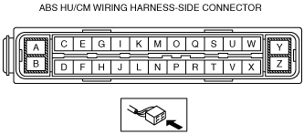
ABS HU/CM INSPECTION
id041300198300
1. Disconnect the ABS HU/CM connector. (See ABS HU/CM REMOVAL/INSTALLATION [L.H.D.].) (See ABS HU/CM REMOVAL/INSTALLATION [R.H.D.].)
2. Connect the negative battery cable. (See BATTERY REMOVAL/INSTALLATION [MZR 1.3, MZR 1.5].) (See BATTERY REMOVAL/INSTALLATION [MZ-CD 1.6].)
3. Attach the tester lead to the ABS HU/CM wiring harness-side connector and inspect the voltage, continuity, or resistance according to the standard (reference value) in the table below.
Standard (reference)
am2zzw00005513
|
|
Terminal |
Signal name |
Connected to |
Measured item |
Measured terminal (measurement condition) |
Standard |
Inspection item(s) |
|---|---|---|---|---|---|---|
|
A
|
—
|
—
|
—
|
—
|
—
|
—
|
|
B
|
Ground
(ABS motor)
|
Ground point
|
Continuity
|
B—ground point
|
Continuity detected
|
• Wiring harness (B—ground point)
|
|
C
|
RR wheel-speed (ground)
|
RR ABS wheel-speed sensor
|
Continuity
|
C—RR ABS wheel-speed sensor connector terminal B
|
Continuity detected
|
• Wiring harness (C—RR ABS wheel-speed sensor connector terminal B)
|
|
D
|
—
|
—
|
—
|
—
|
—
|
—
|
|
E
|
RR wheel-speed
(Signal)
|
RR ABS wheel-speed sensor
|
Continuity
|
E—RR ABS wheel-speed sensor connector terminal A
|
Continuity detected
|
• Wiring harness (E—RR ABS wheel-speed sensor connector terminal A)
|
|
F
|
—
|
—
|
—
|
—
|
—
|
—
|
|
G
|
—
|
—
|
—
|
—
|
—
|
—
|
|
H
|
CAN_H
|
DLC-2
(CAN_H)
|
This terminal is used for communication and cannot be used for malfunction determination during terminal voltage inspection.Perform a DTC inspection.
|
|||
|
I
|
LF wheel-speed
(Signal)
|
LF ABS wheel speed sensor
|
Continuity
|
I—LF ABS wheel-speed sensor connector terminal A
|
Continuity detected
|
• Wiring harness (I—LF ABS wheel-speed sensor connector terminal A)
|
|
J
|
—
|
—
|
—
|
—
|
—
|
—
|
|
K
|
LF wheel-speed
(Ground)
|
ABS wheel-speed sensor (LF)
|
Continuity
|
K—LF ABS wheel-speed sensor connector terminal B
|
Continuity detected
|
• Wiring harness (K—LF ABS wheel-speed sensor connector terminal B)
|
|
L
|
CAN_L
|
DLC-2
(CAN_L)
|
This terminal is used for communication and cannot be used for malfunction determination during terminal voltage inspection.Perform a DTC inspection.
|
|||
|
M
|
—
|
—
|
—
|
—
|
—
|
—
|
|
N
|
Power supply
(System)
|
Ignition switch
|
Voltage
|
Ignition switch ON
|
B+
|
• Wiring harness (N—ignition switch)
|
|
Ignition switch off
|
1 V or less
|
—
|
||||
|
O
|
RF wheel-speed
(Ground)
|
RF ABS wheel-speed sensor
|
Continuity
|
O—RF ABS wheel-speed sensor terminal B
|
Continuity detected
|
• Wiring harness (O—RF ABS wheel-speed sensor connector terminal B)
|
|
P
|
—
|
—
|
—
|
—
|
—
|
—
|
|
Q
|
RF wheel-speed
(Signal)
|
RF ABS wheel-speed sensor
|
Continuity
|
Q—RF ABS wheel-speed sensor terminal A
|
Continuity detected
|
• Wiring harness (Q—RF ABS wheel-speed sensor connector terminal A)
|
|
R
|
—
|
—
|
—
|
—
|
—
|
—
|
|
S
|
—
|
—
|
—
|
—
|
—
|
—
|
|
T
|
—
|
—
|
—
|
—
|
—
|
—
|
|
U
|
LR wheel-speed
(Signal)
|
LR ABS wheel-speed sensor
|
Continuity
|
U—LR ABS wheel-speed sensor connector terminal A
|
Continuity detected
|
• Wiring harness (U—LR ABS wheel-speed sensor connector terminal A)
|
|
V
|
—
|
—
|
—
|
—
|
—
|
—
|
|
W
|
LR wheel-speed
(Ground)
|
LR ABS wheel-speed sensor
|
Continuity
|
W—LR ABS wheel-speed sensor connector terminal B
|
Continuity detected
|
• Wiring harness (W—LR ABS wheel-speed sensor connector terminal B)
|
|
X
|
—
|
—
|
—
|
—
|
—
|
—
|
|
Y
|
Power supply
(Solenoid operation, ABS motor operation)
|
Battery
|
Voltage
|
Under any condition
|
B+
|
• Wiring harness (Y—battery)
|
|
Z
|
—
|
—
|
—
|
—
|
—
|
—
|